Electro Tech is an online community (with over 170,000 members) who enjoy talking about and building electronic circuits, projects and gadgets. To participate you need to register. Registration is free. Click here to register now.
Welcome to our site! Electro Tech is an online community (with over 170,000 members) who enjoy talking about and building electronic circuits, projects and gadgets. To participate you need to register. Registration is free. Click here to register now.
Is it possible to swap out caps or resistors to increase the gain of an inverter (flashes the cathodes based on sound)? Its made up of transistors, resistors, a pot, and capacitors, so what would I be looking for?
Is it possible to swap out caps or resistors to increase the gain of an inverter (flashes the cathodes based on sound)? Its made up of transistors, resistors, a pot, and capacitors, so what would I be looking for?
I think he is trying to get it to flash at normal brightness but respond more to lower sound levels? You need to alter the gain of that first transistor amplifier the mic is connected to. It altered with the resistors surrounding it, but it is probably easier to use a vaiable gain op-amp amplifier in it's place to set it as you wish.
The inverter thats in the schematic has this feature already. I just want to turn the gain up on the amp thats connected to the mic (again, in the schematic). What resistor(s) would I be changing, and would they increase or decrease in value?
The inverter thats in the schematic has this feature already. I just want to turn the gain up on the amp thats connected to the mic (again, in the schematic). What resistor(s) would I be changing, and would they increase or decrease in value?
You could use Bigger Transistors with a higher Hfe. Or, You Could also use a Opamp, or better yet, LM386. It can either have a gain of 20 or 200X, and you can put a filter between 2 pins and have it amplify a certain portion (such as the bass)
Wouldnt it be much simpler (and more compact) just to use the existing circuit and change a resistor? Or is that simply not possible? I want to use what I have, not build something new.
I tried to trace it out as well as possible, but there probably are some errors. Im more concerned about the amplifier portion though. The pot controls the sensitivity of the microphone, and the switch changes between solid-on and sound-activated.
Ah, the pot changes the sensitivity. In that case it's either lower R2 (the 82k) or increase the value of R2. It depends if when you increase the resistance of that pot the gain increases or vice-versa.
I tried to trace it out as well as possible, but there probably are some errors. Im more concerned about the amplifier portion though. The pot controls the sensitivity of the microphone, and the switch changes between solid-on and sound-activated.
The thing is that without having a clear schematic, any suggestions are going to be hit and miss. The inverter section should just involve 2 transistors. The other two transistors are hooked up in some way that isn't obvious - and it doesn't exactly help that the "schematic" (which is understandably cribbed from the layout) is drawn in an utterly backward manner...
Well, In any case, I'd agree with Dr. EM's suggestion, but without understanding how the circuit works, I'm just guessing.
I had to recreate it from the PCB. Being 16 I think thats pretty decent. If it would be easier, I can scan the PCB bottom and overlay the components on the top, but I wont be able to make a better schematic than that. Im also not aware of how the schematic is 'backwards'. Please explain. Thanks.
Generally schematics are drawn with inputs on the left, outputs on the right, minimize the number of overlapping components/lines, keep ground lines on the bottom, or just use ground symbols - it's just a way of keeping things readable. If you can post some reasonable pictures - have the camera facing the board flat on, put a camera on a tripod to minimize changes between repositioning to keep the image scaled properly, and just post the top side and bottom side, I can match up the images either using a image program or just manually eyeball it.
Otherwise it's just playing telephone in a noisy room - information sorta gets through, but not all of it and not all the time...
Hot glue was put there by the factory. Hope these pics will suffice (I didnt have a camera handy). The wires leading off the board go to the microphone pickup thing (temporary fix - glue microphone to speaker and run a 10' cable across the room). **broken link removed** **broken link removed**
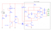
Well, since you took the time to take a photo of it: here's my interpretation:
I downloaded a copy of Electronics Workbench, so I was "learning" it as I went along - so the component values are likely botched up, but I'm pretty sure that this is the configuration. Obviously I'm completely guessing on the transistors, but from the circuit config, it's possible that they're all NPN's.
The thing that really helped out was finding stuff about the Royer oscillator - it's apparently a very common oscillator configuration.
So, given this schematic, what do you think happens when Q4 turns on?
Technically I scanned the board, but thanks nonetheless. So now with a proper schematic, which part would I change? Oh, and about Q4, I can honestly say I have no freakin' clue.
This site uses cookies to help personalise content, tailor your experience and to keep you logged in if you register.
By continuing to use this site, you are consenting to our use of cookies.