ProjectLead
New Member
I am trying to build an iodine clock circuit.
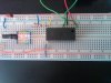
The goal of this circuit is to allow the motor of my car to run while the iodine solution is clear, but to stop when the solution turns black. The iodine solution sits between an LED and a photoresistor. I am using a relay to turn the motor off when there is no light.
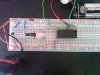
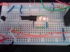
I have attached current photos of the circuit. At this time the LED and photoresistor function properly, but the relay does not trip when the light is removed and my engine continues to turn.
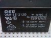
The transistor used is a Mosfet 2N7000 and the Relay is 0MI-SS-212D. The photoresistor was purchased from radio shack and had no specs on it.
I do not have any electrical engineering background, so this circuit has been built through reading articles online. Please let me know how I can improve my circuit.
Thank you.
The goal of this circuit is to allow the motor of my car to run while the iodine solution is clear, but to stop when the solution turns black. The iodine solution sits between an LED and a photoresistor. I am using a relay to turn the motor off when there is no light.
I have attached current photos of the circuit. At this time the LED and photoresistor function properly, but the relay does not trip when the light is removed and my engine continues to turn.
The transistor used is a Mosfet 2N7000 and the Relay is 0MI-SS-212D. The photoresistor was purchased from radio shack and had no specs on it.
I do not have any electrical engineering background, so this circuit has been built through reading articles online. Please let me know how I can improve my circuit.
Thank you.