Electro Tech is an online community (with over 170,000 members) who enjoy talking about and building electronic circuits, projects and gadgets. To participate you need to register. Registration is free. Click here to register now.
Welcome to our site! Electro Tech is an online community (with over 170,000 members) who enjoy talking about and building electronic circuits, projects and gadgets. To participate you need to register. Registration is free. Click here to register now.
That would work. The trick here is knowing exactly what you are trying to do. The distance between the transmitter (light or IR) source and the receiver (detector be it photo transistor or whatever) are important. Therefore if you were up/down counting people for example entering and leaving a room that distance could be a few feet or a meter. Your detector needs to work at that distance. The detector in this circuit needs to be chosen for the application.
IR emitter and detectors are popular because they are not effected by for example room ambient light.
Ok ron from what I am reading here. This detector cannot be used by itself ad would say a pir sensor. It appears I have to use an infrared transmitter with each detector I plan to use. Is that the case?
Yes, that about sums it up nicely. You point an IR transmitter at an IR receiver using a beam of IR light invisible to us. When the beam is broken the receiver reacts. Sometimes it is wise to shield the transmitter and receiver with a small cone to prevent interference. Anyway, you have the idea.
Hi ron me again I have another question. The schematic I sent with the detectors would be the reciever part of the infrared setup right. Can I use a circuit with an infrared led or something of that sort at the other end of the circuit. To connect to it. Any suggestions in that respect would be great.
The last circuit link you sent which shows an IR Emitter and Detector pair. The LED in series with a 270 Ohm resistor is the emitter and Q1 is the detector. Q1 is a PNP type photo transistor sensitive to IR light. When IR light is hitting Q1 it is conducting and the collector (output) is at logic low. When the IR light is interrupted Q1 quits conduction and the output goes high.
You still haven't said exactly what you want to do. If I better knew I could make better suggestions.
Ok rob sorry to be more clear. What I am asking us wha kind of infrared circuit will I use on the end that will keep the phototransustor at logic low. I would assume the conditions for such a circuit would be that it provides an infrared singnal at logic that is two about a meter in length and gives off a narrow beam.
OK, Radio Shack still does sell a basic emitter and detector IR pair. This one was the first I saw with the pair costing $3.49. Something like this is all you need to start experimenting and learning. Matter of fact tomorrow I'll see if my local store has them in stock and hopefully a data sheet for the pair.
Additionally tomorrow I'll throw a few drawings out for you to look at. Then you will understand the whole logic level thing.
hi ron ,
i think i just looked at the same one you got there. i was thinking of dropping by my local store later to see if i got one. i would appreciate more guidance if you have..... thanks.
Ok ron I was wondering what happened to you. I got a pair my self and tried using them together with another NPN transistor and to no avail. There I didn't get it to give me any response. I tried pointing the led at the emmitor and the connecting the base of a 2n2222 transistor to its collector and checking the output at the other transistors collector. Got no type of response. When breaking the line of sight between detector and emmitor I got no response at the output what you think.
OK, I bread boarded real quick a little setup and am attaching the drawing.
This was just the simple Radio Shack part number 276-142 IR Emitter and Detector pair. The specifications are on the package.
IR Emitter:
Reverse Voltage: 5 Volts
Continuous Forward Current: 150 mA
Forward Voltage: 1.3 Volts (1.7 Volts Maximum)
Note: The cathode is the flat side and the shorter of the 2 leads.
IR Detector:
Maximum Collector Current is 50 mA
Note: The collector is the flat side and the shorter of the 2 leads.
I limited the emitter current with R1. It should be below 100 mA with the 47 Ohm 1/4 watt resistor I used so well below the 150 mA maximum but adequate. When you start with things like this it is wise to keep things below maximum ratings.
The IR detector is an NPN Photo Transistor so you don't need another transistor in there. Think of the base as where it receives IR light. That leaves the emitter which is tied to common and the collector which is tied to 5 Volts through a 1.5 K Ohm 1/4 watt resistor to limit the collector current.
Note: You need to limit the current through your emitter and detector or you will toast your components!
I slipped a piece of drinking straw over each, the emitter and detector to help shield against stray light. About an inch long or so. Not the best shield but adequate for this test. I simply aimed them at each other across the bread board.
No light obstruction I got .1 Volts at the line marked Output Signal and when I blocked the light I got 4.5 Volts on the Output Signal line. Those are fine TTL levels for driving the gates.
If you put it together exactly as I drew it it should work fine. I did notice in my original drawing I had the detectors polarity reversed. The cathode sides should have been to common. Also, the original drawing used IR Photo Diodes and not photo transistors.
OK, I bread boarded real quick a little setup and am attaching the drawing.
This was just the simple Radio Shack part number 276-142 IR Emitter and Detector pair. The specifications are on the package.
IR Emitter:
Reverse Voltage: 5 Volts
Continuous Forward Current: 150 mA
Forward Voltage: 1.3 Volts (1.7 Volts Maximum)
Note: The cathode is the flat side and the shIR Detector:
Maximum Collector Current is 50 mA
Note: The collector is the flat side and the shorter of the 2 leads.
I limited the emitter current with R1. It should be below 100 mA with the 47 Ohm 1/4 watt resistor I used so well below the 150 mA maximum but adequate. When you start with things like this it is wise to keep things below maximum ratings.
The IR detector is an NPN Photo Transistor so you don't need another transistor in there. Think of the base as where it receives IR light. That leaves the emitter which is tied to common and the collector which is tied to 5 Volts through a 1.5 K Ohm 1/4 watt resistor to limit the collector current.
Note: You need to limit the current through your emitter and detector or you will toast your components!
I slipped a piece of drinking straw over each, the emitter and detector to help shield against stray light. About an inch long or so. Not the best shield but adequate for this test. I simply aimed them at each other across the bread board.
No light obstruction I got .1 Volts at the line marked Output Signal and when I blocked the light I got 4.5 Volts on the Output Signal line. Those are fine TTL levels for driving the gates.
If you put it together exactly as I drew it it should work fine. I did notice in my original drawing I had the detectors polarity reversed. The cathode sides should have been to common. Also, the original drawing used IR Photo Diodes and not photo transistors.
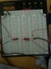
Ok ron. I connected the IR pair just like the schematic instructed. Only difference is I used 4.5 v instead of five and when I ran it it only have me values of 3.3 and 4.4 wilthout and with obstructions respectively. Been at it for the last hour. Any suggestions. Also I used pieces of straw over the leds as recommended by you.
The fact that you now see change tells us something is working. The fact that with the unobstructed IR path you see such a high level tells us that for some reason the photo transistor (receiver) isn't seeing much light.
I only used the short piece of drinking straw as a shield of sorts so you may want to mess with that. Something else you can try is if you have an IR TV remote point it at the receiver and push a few buttons and see if the thing reacts. Keep in mind any IR remote device will transmit pulses so it may look weird.
Based on your last post either the transmitter (emitter) isn't putting much out or the receiver isn't seeing it. I also don't know what the previous setup you tried may have done to the receiver or transmitter.
It looks pretty much like what I threw together. Maybe it is just me but I don't see one power line to the receiver? I also just for the heck of it did aim the TV remote at it and got a reaction. I din't bother to connect a scope to see the pulse trains from the remote. I can't understand why it won't work for you if it is exactly like the drawing I did. There is so little to this thing. Weird.
This site uses cookies to help personalise content, tailor your experience and to keep you logged in if you register.
By continuing to use this site, you are consenting to our use of cookies.

")