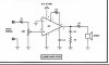
hey all, im kinda new in a word of electronics, so im learning now how amplifier works. now i found this circuit that shows a sample of it. but then i saw a very weird method of using electrolyte capacitors. as far as i know, capacitors can charge voltage into them selfs to stebalize the voltage and i know that its NOT conducting any voltage between the pins. now check out that circuit that i found and tell me whats wrong what that..
thanks.
thanks.