Hello everyone
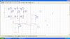
I'm designing an single phase Impedance source power inverter which provides both buck and boost operation. My aim is to keep the output AC voltage constant(20v peak) for two conditions
1.Input less than output (I/p-13.5 D.C,O/p-20vpeak)
2.Input greater than output( I/p-25 to 33.3 DC O/P-20vpeak)
My load resistance is constant at 12ohm. I'm using Sinusoidal PWM technique for switching my MOSFETS. My switching frequency is 10Khz and output frequency is 50 Hz.
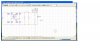
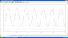
I've simulated the circuit using MATLAB and got the output,now i need to design a LC filter at the output stage. I tried different values of L and C,i've got the frequency to be 50 Hz but the load voltage is greatly varying.
For the first case when my I/P is less than O/P without the filter i got 20v peak but with filter my output is reduced to 5 Vpeak. Now when i use the same filter values for my second case i'm getting the output to be around 25V.
SO Basically how do i design a optimum filter values that works for both my cases. What are the steps in doing so? The output volage needs to be 20V peak(atleast around 19v),cant compromise on that and frequency at 50 HZ.
Thanks in advance
I'm designing an single phase Impedance source power inverter which provides both buck and boost operation. My aim is to keep the output AC voltage constant(20v peak) for two conditions
1.Input less than output (I/p-13.5 D.C,O/p-20vpeak)
2.Input greater than output( I/p-25 to 33.3 DC O/P-20vpeak)
My load resistance is constant at 12ohm. I'm using Sinusoidal PWM technique for switching my MOSFETS. My switching frequency is 10Khz and output frequency is 50 Hz.
I've simulated the circuit using MATLAB and got the output,now i need to design a LC filter at the output stage. I tried different values of L and C,i've got the frequency to be 50 Hz but the load voltage is greatly varying.
For the first case when my I/P is less than O/P without the filter i got 20v peak but with filter my output is reduced to 5 Vpeak. Now when i use the same filter values for my second case i'm getting the output to be around 25V.
SO Basically how do i design a optimum filter values that works for both my cases. What are the steps in doing so? The output volage needs to be 20V peak(atleast around 19v),cant compromise on that and frequency at 50 HZ.
Thanks in advance