Electro Tech is an online community (with over 170,000 members) who enjoy talking about and building electronic circuits, projects and gadgets. To participate you need to register. Registration is free. Click here to register now.
Welcome to our site! Electro Tech is an online community (with over 170,000 members) who enjoy talking about and building electronic circuits, projects and gadgets. To participate you need to register. Registration is free. Click here to register now.
hmmm
this i have to see.if the front and back lamps are connected in parallel then it will the good for me.i can connect this circuit in parallel.
if they are in series then i shld think what to do.
The lamps are parallel for shure. You can see that by the lamp being grounded. The only thing you have to check is that usually the turn-signal relays are "load dependant". This can be seen when one lamp "blows" is usually flashes very fast to warn the driver about this condition. If you are to remove the front lamp you can do one of two things: Replace the rear lamp by a stronger (more wattage) lamp or place a resistor of the equivalent value of a lamp in parallel with the circuit lo "load" the turn-signal relay.
steev said:
hmmm
this i have to see.if the front and back lamps are connected in parallel then it will the good for me.i can connect this circuit in parallel.
if they are in series then i shld think what to do.
give me some time guys.i got all of the components(with exact zener ratings).tomorrow i'll populate then and wll post the results.
any formula to calculate the requited resistance value? to compensate the load
Check first if the relay is load dependant or give me the lamp wattage. to limit the power dissipation in the resistor we can increase a little the rear lamp to reduce the resistor power.
steev said:
give me some time guys.i got all of the components(with exact zener ratings).tomorrow i'll populate then and wll post the results.
any formula to calculate the requited resistance value? to compensate the load
Can somebody explain to me why this circuit wouldn't work in parallel with one or both of the lamps? I can understand that the current draw might have an effect on the flash rate of the turn signal, but that's about all I can come up with.
It will work fine. The problem is if you remove the lamp. The circuit will only draw about 30mA per led
Darth Bagel said:
Can somebody explain to me why this circuit wouldn't work in parallel with one or both of the lamps? I can understand that the current draw might have an effect on the flash rate of the turn signal, but that's about all I can come up with.
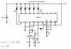
It will be difficult to get even time separation for the LED turn-ons if you try to use zeners. The exponential nature of the cap charge, combined with the ever increasing load as the zeners conduct, exacerbates this problem. if you want to pursue an all-discrete solution, you can use a current source to charge the cap, buffer it with an emitter follower, and use cascaded emitter followers (or diodes) for the level shifting. Emitter followers seemed to have slightly better linearity in the simulation. I have posted a schematic below.
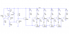
I think that an LM3914 would be simpler, if the all-analog solution is to be pursued. I have posted a possible solution below, which has not been tested or simulated.
A 555 and a 5- or 6-bit shift register, or a 555 with a binary counter and some decoding logic, is also a possibility. A PIC would certainly be simpler from a hardware point of view, except that it requires a voltage regulator. Any digital solution would have to deal with the noisy power supply of a vehicle. The analog solutions have an advantage in this respect.
i populated the circuit on pcb board,it worked but not similar in all the times.when the engine is at a particular RPM they LIT fast and the RPM is low they lit slow.
may be this is what "roff" said.
@roff
ur LM3914 circuit looks good.but i don't understand how the cycle starts and ends.is it gona give me the exact pattern?imean 1+2+3+4+5.....
Try to regulate th voltage by putting a 12V zener at the supply with a 100ohm resistor in series. It will maintain the voltage stable
steev said:
i populated the circuit on pcb board,it worked but not similar in all the times.when the engine is at a particular RPM they LIT fast and the RPM is low they lit slow.
may be this is what "roff" said.
@roff
ur LM3914 circuit looks good.but i don't understand how the cycle starts and ends.is it gona give me the exact pattern?imean 1+2+3+4+5.....
Here is the simulation of Ferreira's circuit. I tweaked the value of R13 to give the best spacing I could achieve. I also had to guess at the pulse width and duty cycle of the turn signal "relay".
I have attached the LTspice file in case someone wants to run the simulation.
The only way to tune each led would be using 5 voltage deviding trimmers and the same value zener for all the nodes. This way you could set the trigger voltage of each node.
Roff said:
Here is the simulation of Ferreira's circuit. I tweaked the value of R13 to give the best spacing I could achieve. I also had to guess at the pulse width and duty cycle of the turn signal "relay".
I have attached the LTspice file in case someone wants to run the simulation.
i populated the circuit on pcb board,it worked but not similar in all the times.when the engine is at a particular RPM they LIT fast and the RPM is low they lit slow.
may be this is what "roff" said.
@roff
ur LM3914 circuit looks good.but i don't understand how the cycle starts and ends.is it gona give me the exact pattern?imean 1+2+3+4+5.....
The only way to tune each led would be using 5 voltage deviding trimmers and the same value zener for all the nodes. This way you could set the trigger voltage of each node.
This site uses cookies to help personalise content, tailor your experience and to keep you logged in if you register.
By continuing to use this site, you are consenting to our use of cookies.