me_shaurya
New Member
Hi, I'm new to electronics but have some prior experience with robotics. I'm currently working on a project that involves creating a TENS unit and a shock generator, all within the compact form factor of a wristwatch.
I've selected the following components for the design:
1. LPR6235-752SMR – Coupled Inductor
2. 470µF 450V Ceramic Capacitor
3. UF4007 – Diode
4. SL5N50D, AO3434A, or IRLR7843 – MOSFET options
I'll be using the XIAO ESP32-S3, which provides a PWM signal with a voltage range of 0–3.3V.
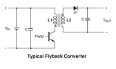
However, I'm facing challenges in finalizing the most efficient and safe circuit to achieve a variable output of 0 to 300V. I've attached an example circuit from the coupled inductor's datasheet.
Could someone also help me theoretically calculate the output voltage and component behavior before I test it physically?
I've selected the following components for the design:
1. LPR6235-752SMR – Coupled Inductor
2. 470µF 450V Ceramic Capacitor
3. UF4007 – Diode
4. SL5N50D, AO3434A, or IRLR7843 – MOSFET options
I'll be using the XIAO ESP32-S3, which provides a PWM signal with a voltage range of 0–3.3V.
However, I'm facing challenges in finalizing the most efficient and safe circuit to achieve a variable output of 0 to 300V. I've attached an example circuit from the coupled inductor's datasheet.
Could someone also help me theoretically calculate the output voltage and component behavior before I test it physically?