Electro Tech is an online community (with over 170,000 members) who enjoy talking about and building electronic circuits, projects and gadgets. To participate you need to register. Registration is free. Click here to register now.
Welcome to our site! Electro Tech is an online community (with over 170,000 members) who enjoy talking about and building electronic circuits, projects and gadgets. To participate you need to register. Registration is free. Click here to register now.
alec_t,
How are you calculating the gain? I may have a different interpretation of how to calculate the gain since the schamatic giving in post #16 is different from what I have seen before. This is new stuff to me and do not know how to interpret it.
Thanks
On the circuits that I am creating, the second stage, which is a Common Collector, I a gain of about 6. How or what resistors determine the gain. I am also face with the problem of the bottom swing having more gain the the top swing and in some cases saturating. What do I do? I was thinking on adding a third stage but with a gain of 5 for a total gain of 30 (5x6). I already look at some formulas relating to gain but for some reason I am not getting any good results when i aply them.
Can you post your circuit?
In theory, gain for an amplifier stage using a single transistor of infinite beta can generally be calculated from a formula as a function of two resistors. However, beta is never infinite and the resistors may be loaded by impedances of neighbouring stages, so reality rarely agrees with theory.
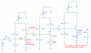
Here is the circuit that I am simulating. When I simulate the last two stages using an input of 1 mVpk I get a gain of about 6 but if I add another stage (as in this circuit) then the circuit saturates at both ends and there is a gain of about 45 on the top swing and a gain of about 80 on the bottom swing. That is really weird.
I wish you would turn off the chicken-pox dots on your schematic.
You should look at DC voltages in your SIM:
1) The first two transistors are saturated so cannot amplify anything.
2) The output transistor does not have enough base current.
3) Why use a class-A circuit instead of a class-AB circuit??
This site uses cookies to help personalise content, tailor your experience and to keep you logged in if you register.
By continuing to use this site, you are consenting to our use of cookies.