Ryan Harding
New Member
Hi, i have a friend who is currently undergoing his GCSE project. For the people who dont understand GCSE's, its the examinations for 15-16 year olds. The english first recognisable grades, im unsure of what the equivelant of this is to the USA or any others.
He is doing resistant materials, wood/metal/plasitcs. His task is to create a wooden toy that moves, something along these lines. He has asked me to install some basic electronics in a tractor!
So we have brifely talked about what may be 'acceptable?' Basically practable and actually useful")
The ideas so far are, in my opinion, very basic electronics:
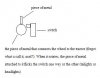
Headlights! - I think that this maybe is boring and un origional! So i think that a simple circuit using some resistors, transistor and an LDR would be more useable? No switches, and in my opinion more impressive!
Most tractors, here in the U.K, have orange flashing lights on the top. A flashing orange LED would fit right in here, ideal.
This is one that i am unsure about:
2 Red LED's that light up when the tractor is reversing, and a buzzer that buzz's for a second and then stops, starts etc, maybe with a 555 chip? I'm unsure of this as the vehical is mechanical, not electronic so i dont know how it would sense that it is reversing?
Suggestions for that would help me alot.
Now to the problem that i am really after!
(You didn't think that was all did you )
I have made the 'automatic headlamps,' before. Not for the same purpose, more for experimental purposes, but i'm sure that it can be modifyed to suit the needs.
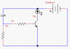
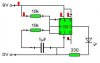
I have the following circuit that i used, but im unsure of what parts to have!
1) The battery and im guessing can be 2x 1.5v batteries? 3v is enough to run this small circuit?
2) What is the differnce in LDR's, i have only used them once, and was given the part.
3) Transistor. I have used one of these in the circuit and know for a fact that it was a 'NPN' transistor. It came on at 0.6v, sorry if this is wrong, im new to transistors, havent used them much at all!
So an over view of what im asking, is there a way for the reversing plan, to be put into action?
What circuit components would i need to make the automatic headlights?
Sorry if you find this post is too big, i just dislike it when people post and dont give the whole story, it leaves questions un answered and people irritated!!
Thanks very much,
Ryan Harding
He is doing resistant materials, wood/metal/plasitcs. His task is to create a wooden toy that moves, something along these lines. He has asked me to install some basic electronics in a tractor!
So we have brifely talked about what may be 'acceptable?' Basically practable and actually useful
The ideas so far are, in my opinion, very basic electronics:
Headlights! - I think that this maybe is boring and un origional! So i think that a simple circuit using some resistors, transistor and an LDR would be more useable? No switches, and in my opinion more impressive!
Most tractors, here in the U.K, have orange flashing lights on the top. A flashing orange LED would fit right in here, ideal.
This is one that i am unsure about:
2 Red LED's that light up when the tractor is reversing, and a buzzer that buzz's for a second and then stops, starts etc, maybe with a 555 chip? I'm unsure of this as the vehical is mechanical, not electronic so i dont know how it would sense that it is reversing?
Suggestions for that would help me alot.
Now to the problem that i am really after!
(You didn't think that was all did you
)I have made the 'automatic headlamps,' before. Not for the same purpose, more for experimental purposes, but i'm sure that it can be modifyed to suit the needs.
I have the following circuit that i used, but im unsure of what parts to have!
1) The battery and im guessing can be 2x 1.5v batteries? 3v is enough to run this small circuit?
2) What is the differnce in LDR's, i have only used them once, and was given the part.
3) Transistor. I have used one of these in the circuit and know for a fact that it was a 'NPN' transistor. It came on at 0.6v, sorry if this is wrong, im new to transistors, havent used them much at all!
So an over view of what im asking, is there a way for the reversing plan, to be put into action?
What circuit components would i need to make the automatic headlights?
Sorry if you find this post is too big, i just dislike it when people post and dont give the whole story, it leaves questions un answered and people irritated!!
Thanks very much,
Ryan Harding