Continue to Site

Welcome to our site!

Electro Tech is an online community (with over 170,000 members) who enjoy talking about and building electronic circuits, projects and gadgets. To participate you need to register. Registration is free. Click here to register now.

  • Welcome to our site! Electro Tech is an online community (with over 170,000 members) who enjoy talking about and building electronic circuits, projects and gadgets. To participate you need to register. Registration is free. Click here to register now.

Question regarding the circuit

Status
Not open for further replies.

rubberlele

New Member
Hi!
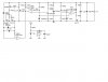
I've connected the circuit, for now, i leave the left part(to solar panel) and right part(to load) unconnected. What i have in mind is, i wanna test connecting the battery at the center of the circuit and then look at the output at the right side(to load) in terms of what voltage and current will come out. However, when i wanna connect to battery, sparks will come out at the wire connecting the battery to the circuit, is anything wrong with this?
 

Attachments

  • chargercircuit1.jpg
    chargercircuit1.jpg
    39.3 KB · Views: 765
I've double checked the connection, and all seems okay, but the sparks still there, and 1 more thing, I replaced the BS170 with MTP2P50E, izzit the cause for the spark? i think nope...huhu..headache
 
the BAT82 diode pointing left (at the bottom left-hand side of your circuit) is causing the spark problem.

When you picture it, the source, destination and diode are connected in series, forming a complete circuit.

That diode should be removed, replaced with a high value resistor, or replaced with a capacitor. If you are following a design from a book, then tell me the name of the book, because I'm not buying it.
 
mstechca said:
the BAT82 diode pointing left (at the bottom left-hand side of your circuit) is causing the spark problem.

When you picture it, the source, destination and diode are connected in series, forming a complete circuit.

That diode should be removed, replaced with a high value resistor, or replaced with a capacitor. If you are following a design from a book, then tell me the name of the book, because I'm not buying it.
1. Rubberlele says the solar cell is disconnected.
2. There is a 100k resistor in series with the diode.
 
rubberlele said:
mm Ron, does it cause the sparks?
I don't know what causes the sparks. I was just refuting mstecha's explanation. There is nothing in the circuit that I can see that would cause high current to flow when you connect the battery.
Have you checked the polarity of the MBR745? If it is backwards, it will short out the battery - and probably be destroyed.
EDIT:
The comment about the MBR745 is not totally correct. The BUZ11 on the load side should be initially OFF (due to 47uF capacitor), although it could subsequently turn on, depending on the 25k pot setting. If the diode is reversed, it could then short out the battery, and probably destroy the diode or the BUZ11 or the battery, or any combination of the above. :cry:
 
i did, and it seems okay with me...and Ron, would you care to review my flow sensor thread? hmm i dunno whats wrong with this charger circuit...headache...
 
For checking you can connect a serial resistor to battery and an amp meter serial, too, then connect and see if the high current is steady or happens just for a very short time (while the 1000uF cap is charged).

Oops I just noticed the time constant of the 150k resistor and 47u cap is many seconds so no spark should come immediately as the battery is connected. The comparator turns on the BUZ11 on the right only a few seconds after the power supply is connected, or may not even turn it on, if the battery voltage is too low.
 
The BS170 cannot be replaced with MTP2P50E.
BS 170 is N-channel, MTP2P50E is P-channel MOSFET. This particular change cannot cause the sparks, but the circuit will not work with MTP2P50E.

Check also that there is no short circuit between Vbat and GND before anything else.
 
oops, I forgot the 100K resistor.

Like Ron Said, if you connected the diode on the far right the wrong way, the circuit will short (create sparks upon battery contact) because that is the path the current will go through.

Why is that diode (on the far right) there?

and never mind what I said about the diodes on the left. I forgot to look at the 100K resistor.
 
I forgot to mention that Generis does have a point.

Let's take it simple.

If you take a battery and a capacitor and connect it one way and let it charge (say about 10 seconds), and then swap the connections (opposite polarity), the connection will make a blue spark because you are forcing the capacitor to charge in the opposite direction faster than usual.

In order to experience this the best, you need a decent battery, and a high value capacitor. (at least 100uF)
 
the diode is there because of the load i think, mmm i'll replace back the MTP2P50E with BS170 later on, hmmm if im not wrong, the spark will come out instantly when i wanna connect the battery
 
I think it is better to remove the diode (on the far right) as a start.

then maybe you can get better results when you try the circuit.
 
Status
Not open for further replies.

Latest threads

New Articles From Microcontroller Tips

Back
Top