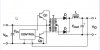
I am building a boost circuit that convert 12v to 24v with 4A in output.
I am realy confused about inductor part! Is this topology like flyback? or forward?
In flyback transformer needs air gap but in forward don`t.
What should I do for self in my circuit? With air gap or without ?
I am realy confused about inductor part! Is this topology like flyback? or forward?
In flyback transformer needs air gap but in forward don`t.
What should I do for self in my circuit? With air gap or without ?