Continue to Site

Welcome to our site!

Electro Tech is an online community (with over 170,000 members) who enjoy talking about and building electronic circuits, projects and gadgets. To participate you need to register. Registration is free. Click here to register now.

  • Welcome to our site! Electro Tech is an online community (with over 170,000 members) who enjoy talking about and building electronic circuits, projects and gadgets. To participate you need to register. Registration is free. Click here to register now.

Stun Gun

Status
Not open for further replies.
help

did you find it ?
if you find it please send me the details
thanks


mahjosh said:
Could you please provide more details on the transformer.
Is it the output transformer used in pockect radio sets?

Thanks
 
The circuit must be 40 years old. Travel back in time about 40 years and buy the transformer. It is not the output transformer from a little portable radio.

I remember 40 years ago when I could buy the transformer at the electronic parts store. I know a surplus electronics parts store that has lots of old junk and I bet they still have some.

But the circuit will not make a stun gun. It will just make a little spark.
 
tytower said:
I use it to zap any simple, kind, friendly and cute animals I come accross. They don't come back for more , they do not pass go ,they are not pests anymore.

Hmmm, some serious irony there. Since when did "simple, kind, friendly and cute animals" equate to being "pests"? Geeez, I hope you don't apply that philosophy to humans!
 
What ........?????

What is the application of stun gun........?????

ElectroMaster said:
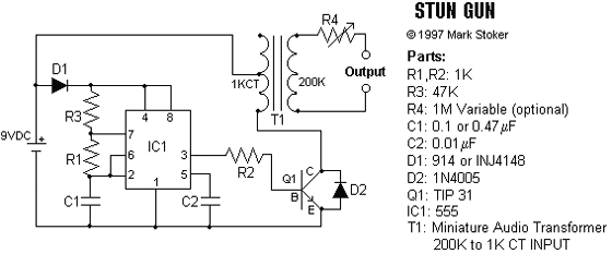
This stun gun is powered by a 9V battery. The transformer steps up the voltage to about 1800V (but with very low current). A 555 timer IC is used to generate a high-frequency output. A 1 MEG variable resistor can also be used at the output to drop the voltage, but this is optional. If you build this circuit, be careful, as it outputs a high voltage. Touching the output leads will induce a painful shock.

stun_gun.gif


NOTE: Building stun guns can be very dangerous! Please use caution.
 
satech said:
What is the application of stun gun........?????

you're "stunned" when you discover that it doesn't perform very well for the time, effort, and cost you wasted on it.
 
This circuit is not a Stun Gun. It is just a little spark generator.
A Stun Gun makes a continuous high power high voltage shock.
This little circuit makes a very weak shock.

You can make it any way you want.
 
tytower said:
I use it to zap any simple, kind, friendly and cute animals I come accross. They don't come back for more , they do not pass go ,they are not pests anymore.


That is sick, although having cruel thoughts about one of the neighbor's cat's... Craps in my yard, usually in a high traffic area (guess the grass is shorter), and doesn't bother covering it up. Every cat I ever owned made such a huge deal of digging out a hole, then filling it over when done. This one just squats and drops, and walks. All usually quicker than I can notice on the security cameras.

Wonder if this cat would be stupid enough to eat out of a metal dog bowl...
 
I doubt that even a stupid cat would eat from your metal bowl that makes "crackling" noises.
 
I've read that cats cover their crap so it doesn't offent the dominant animals (their human owners). Perhaps the cat that craps in your garden is an alpha cat, it's probably either a stray or it has its owners under its thumb or perhaps I should say claws.
 
a 5kV megger is very effective.

I had a dog steal our cat food usually at night.

One day put the cat food outside, and kept our cats inside.

Put the plastic cattray on an aluminium plate on top of a rubber mat.
made surrounding concrete floor damp.

Connected 5kV megger (AVO BM 25) and monitored from the window.

Dog arrived, connected HV lead with HV gloves while megger was on.

Lots of noise, Dog ran away like a torpedo.

Never came back to steal our catfood.
 
Careful now, you could end up killing someone with that if it's not sufficiently current limited.
 
Last edited:
Sceadwian said:
Careful now, you could end up killing someone with that if it's not sufficiently current limited.

Seems like if 'someone' has been eating the pet food, they have bigger worries... That big recall few weeks ago was really Shocking. You'd think there would be some minimal for of quality control. A biological contaminate could easily be transfered to pet owners, not mention I still believe the urban legend about senior citizens... Fixed incomes and high priced prescriptions, old people are always popping pills, can't all be vitamins.
 
Some Megger s are current limited to such an extent that they can't shock you at all.
 
just checking

I was looking at the "stun gun" design and came across this website.

**broken link removed**

This person is using 1200:8 ohm transformer. Does this mean that in order to get the transformer "working" you need 1.125 amps on the primary (9 volts/8 ohms).

1) Can a 9 volt supply 1.125 amps?
2) Power= VI, 9*1.125= 10 watts

Using (Z1/Z2)^(1/2)=N1/N2=I2/I1

(8/1200)^(1/2)=0.0816

I2=0.0816*1.125=0.091 amps

Therefore on the secondary you get 0.091 amps.
 
darshelectro said:
This person is using 1200:8 ohm transformer. Does this mean that in order to get the transformer "working" you need 1.125 amps on the primary (9 volts/8 ohms)?
Only if the 9V supply is regulated and only if the transformer has a 1200 ohms load. It has a high load resistance so the 8 ohms winding has a low current and the output also has a low current.

1) Can a 9 volt battery supply 1.125 amps?
Only for a moment but the voltage will be much less than 9V.
 
trying to understand

rather then just building it, I’m trying to understand how people have calculated the values for various components for the stun gun picture attached.

Looking at this person website for some help (and also using my brain):
http://www.kpsec.freeuk.com/trancirc.htm

To calculate the base resistance for the transistor (tip 31) you need voltage and current:

First, using basic ohms law.

- The difference between the emitter and base should be about 0.6 V
i know the output voltage from the 555 timer is about 1.7 v less then Vcc. so if you have 9 volt supply then 7.3 Volt would on pin 3.

so therefore the voltage difference across the base resistance would be 7.3-0.6 = 6.7 Volts. ok

Now for the current.

(Using the above website and the attached datasheet for tip31)

The load current is 9 volts/8 ohms =1.125 amps

Using the datasheet attached, looking at the graph of Ic vs Hfe, 1000 mA, hfe is about 100.

Therefore Ib current is about 1.125/100=0.01125 amps.

Therefore the resistance would be about 6.7/0.01125=600 ohms
if you use the method as described by the website, you would get about 130 ohms.

i can see 600ohms is close to 1000ohms, but if you used 1000 ohms, would you not get about 0.67 amps passing through the transformer. Or is my understanding flawed.

At the moment I am having difficulty trying to get this circuit to work. I can get the 555 timer to work, but when it comes to getting a voltage across the transformer I get nothing.

I can get current flowing through the base of the transistor, but it is a lot lower then I have calculated even with a fresh battery.

Can someone correct me if I’m wrong about the above.
 

Attachments

  • stun_gun.gif
    stun_gun.gif
    14.6 KB · Views: 1,433
  • TIP31.pdf
    37.7 KB · Views: 830
It depends on the size of your 9V battery, one of those large 9V batteries (the kind used in transistor radios) will, a small 9V battery (the kind used in a smoke alarm) won't. The maximum current available will depend on the impedance of your battery, the kind of 9V battery here probab;y has an impedance of about 30:eek:hm: and therefore won't supply more than 300mA even when short circuited.

**broken link removed**
 
darshelectro said:
Using the datasheet attached, looking at the graph of Ic vs Hfe, 1000 mA, hfe is about 100.

Therefore Ib current is about 1.125/100=0.01125 amps.
Hfe is used to design a linear amplifier, not a switch. If the collector current is 1.125A and the base current is only 1125mA/100= 11.25mA then it would not saturate. Its collector voltage would be about 4V for most of them.
The datasheet spec's a low saturation voltage of 1.2V max if its collector current is 3A and its base current is 375mA. The graph of typical saturation voltages has the base current at 1/10th of the collector current.

At the moment I am having difficulty trying to get this circuit to work. I can get the 555 timer to work, but when it comes to getting a voltage across the transformer I get nothing.
Look at the picture of the TIP31's pins on its datasheet. Maybe you have them connected backwards.

I can get current flowing through the base of the transistor, but it is a lot lower then I have calculated even with a fresh battery.
The base current is in fast pulses. You need an oscilloscope to measure them.
 
will it work

well, if over 300mA is needed on the base of the transistor, and if i remember correctly the 555 timer can only deliver a max of 200mA. How can this circuit work?:confused:
 
Status
Not open for further replies.

Latest threads

Back
Top