Continue to Site

Welcome to our site!

Electro Tech is an online community (with over 170,000 members) who enjoy talking about and building electronic circuits, projects and gadgets. To participate you need to register. Registration is free. Click here to register now.

  • Welcome to our site! Electro Tech is an online community (with over 170,000 members) who enjoy talking about and building electronic circuits, projects and gadgets. To participate you need to register. Registration is free. Click here to register now.

TCI Ignition project

Status
Not open for further replies.

mostafa_gordy

New Member
hi everyone.... :D
I sorry my english is poor ......
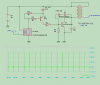
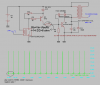
I plan to design a TCI circuit for old kettring ignition system(points breaker distributor) of my car .....
I want to drive a TCI coil (1 ohm Primary impedance) .

please see my schematic and :

1-this schematics is true or false?
2-if true, need whats change for optimized ?( only optimization of driver, not change power Transistor (BUX15) because I have not ANY other high voltage transistor !
 

Attachments

  • tci simulation.PNG
    tci simulation.PNG
    13 KB · Views: 1,430
effect adding flywheel Diode ...

after adding flywheel in circuit =decrease negative spike ........
Is this result bad in ignition gasolin and air mixture in cylinder .....?
bux15 is Vce=500v Ic 8A Ib=2a hfe=15-60
 

Attachments

  • tci 2 simulation.PNG
    tci 2 simulation.PNG
    7.6 KB · Views: 1,404
No you can't use a flywheel diode on the coil. You want all the back-ENF energy to go to the sparkplug.

I would put a resistor in series with C1 so the pair acts as a RC snubber to limit Q1 peak Vce. And use a 1500v Vce minimum rated transistor for Q1.

Your 300v zener pair will likely destroy itself, so remove it or put a resistor in series, personally I would remove it (once you have the RC snubber sorted out).

You should run a filtered DC supply for Q2, so I would add a small resistor and large cap after the diode, to give about 10-11v DC wihtout any noise from the 12v rail being present.

R5 and R4 are too low, a few hundred ohms would be better. R3 and base resistor values probably need to be adjusted.
 
STGW40NC60V IGBT 600V 260W 80A (TO-247) is suitable for driving 1 ohm ignition coil ?
what is suitable schmatics? please post schmatics
 
STGW40NC60V IGBT 600V 260W 80A (TO-247) is suitable for driving 1 ohm ignition coil ?
...

Not really, you don't need an 80A transistor as coils are only about 3-5 amps when ON, and at 40% duty.

And you would be better with something much higher than 600v.

I would look at a large TV HOUT transistor; 1500v Vce or more, and 10A or so should be enough.

Have a google around the internet for schematics, there should be a lot. :)
 
A 3 ohm coil is pretty typical;
I= E/R I=12/3 I=4A.

So you need a transistor capable of switching >4 amps at about a 40% duty cycle. Any power transistor capable of 8A or more should be fine.

Vce is the maiximum voltage the transistor will take between collector and emitter, before it is destroyed. You want the Vce value to be very high. Since 1500v and 2000v Vce transistors are commonly available for television use I would use one of those. You can get one of these transistors from inside any old (big) CRT televisions.

It sounds like you need more experience and more information to build this ignition system, I suggest you do some reading of other people's DIY ignition systems, and see how they solved the common problems. I'm NOT going to design the whole ignition system for you. :)
 
Status
Not open for further replies.

Latest threads

Back
Top