Continue to Site

Welcome to our site!

Electro Tech is an online community (with over 170,000 members) who enjoy talking about and building electronic circuits, projects and gadgets. To participate you need to register. Registration is free. Click here to register now.

  • Welcome to our site! Electro Tech is an online community (with over 170,000 members) who enjoy talking about and building electronic circuits, projects and gadgets. To participate you need to register. Registration is free. Click here to register now.

Transformer help

Status
Not open for further replies.

Twangin4u

New Member
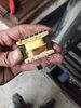
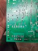
Hello I was hoping someone could shed some light on this transformer. It goes to my oven and I'm trying to identify it so I can buy a replacement to solder back on the board. I've never dismantled a transformer before but this particular one has me scratching my head. The input wires go directly into what appears to be a transistor? Which was taped to the first winding. An explanation of how this works would be cool.. even cooler what are the specs of this thing so I can order replacement.
Thank you
 

Attachments

  • 20201102_222735.jpg
    20201102_222735.jpg
    1.1 MB · Views: 214
  • 20201102_222758.jpg
    20201102_222758.jpg
    1.2 MB · Views: 206
  • 20201102_222809.jpg
    20201102_222809.jpg
    1.2 MB · Views: 230
The device in the windings is a thermal fuse, it's there to disconnect power and prevent a fire, in case of a fault.
They are very common in appliance transformers.

The transformer part number turns up an appliance model with a schematic ; Jenn-Air SVE87600B or Maytag???

If that is correct, the transformer is presumably 110V primary with a 10-0-10V secondary, and this is the oven control schematic.
It looks like there may be three of those transformers in it, if this is the correct thing?


0029091064_4.gif
 
Oh thank you. Yes it's a jenn-air/maytag double oven. This particular oven has only 2 transformers. They both got fried. Now the search for the replacement with the fuse.
Thanks again
 
I'm having a hell of a time trying to find this transformer. My lack of understanding is most of the problem on sure..
Here is the folded schematic I found in the oven...

So I'm assuming this would be 115v input. 10-0-10 vac output? So this would have a center tap of 0v?
The transformer has 12 through hole pins and I'm even having a hard time finding that...

Any push in the right direction would be greatly appreciated.

Hoping to buy 2 small transformers and be done with it instead of shelling out for new oven for Turkey day
Thanks
 

Attachments

  • 20201104_183500.jpg
    20201104_183500.jpg
    1.5 MB · Views: 178
I suggest that you use these:- https://www.digikey.co.uk/product-detail/en/talema-group-llc/62051/1295-1073-ND/3881358

You will need to mount them somewhere else, maybe on the metalwork, but they only need one mounting bolt each. Toroidal transformers usually come with a round metal plate, two round foam pads and a bolt. The bolt clamps the transformer between the metal plate and a flat metal surface that needs to have a hole drilled for the bolt. The foam pads go between the transformer and the metal to even out the pressure.

The transformers I suggested are 9 V, not 10 V, but that probably doesn't matter. A transformer is at its rated voltage at full load, so the original transformers would have been a bit above 10 V, probably nearly 12 V, with no load, dropping to 10 V at full load. The replacements that I've suggested are larger and have a higher rating, so they won't drop as much, and they start at 10.5 V with no load.

Also, you can add a few turns to a toroidal transformer quite easily by just threading ordinary wire through the hole in the centre and around the outside. Each pass through will add about 1/8 V for that size of transformer, so adding 1 Volt isn't a big deal. There's a short thread here https://www.electro-tech-online.com/threads/kef-psw2500-active-base-unit-repair.159244/ about adding a second winding to a transformer. To add voltage, you just put a few turns in series with the existing windings. If the voltage goes down not up, reverse the direction of the additional windings.

The suggested transformer has dual primary winding and dual secondary windings. You have to connect it correctly and as it has wires not pins, you have to be methodical. The schematic of the transformer is on page 8 of the data sheet https://talema.com/wp-content/uploads/datasheets/Transformer-Catalog.pdf

To connect the primary windings to 120 V you connect the live wire to brown and grey, and you connect the neutral to blue and violet.

On the secondaries, the two circuit diagrams are different. One shows the windings connected in series, and the other shows them as separate windings. The transformer that you have has a few spare pins so it's not clear which ones are actually used. If you post a picture of the circuit board that show the tracks, we can probably tell you how to connect up the secondaries.
 
Pins 2&3 are input and pins 7,9,12 are the secondary.
Seems strange that an exact replacement isn't more readily available. There's literally thousands of different transformers. Maybe I need to dig deeper. The existing transformers had a built in fuse. Do they all have a fuse?

I can buy the whole boards for around $150/each but seems silly when I just need the transformers
 

Attachments

  • 20201104_223855.jpg
    20201104_223855.jpg
    1.6 MB · Views: 188
  • 20201104_223846.jpg
    20201104_223846.jpg
    1.5 MB · Views: 197
  • 20201104_223821.jpg
    20201104_223821.jpg
    1.3 MB · Views: 172
  • 20201104_223813.jpg
    20201104_223813.jpg
    1.2 MB · Views: 182
  • 20201104_223830.jpg
    20201104_223830.jpg
    1.6 MB · Views: 179
With there only being 3 pins that are the secondary, if you use the transformer that I suggested you need to connect both yellow and black to where pin 9 goes, and red to pin 7 and orange to pin 12. There are other ways that would work.

Pin 2 should go to brown and grey, and pin 3 to blue and violet.

The toroidal transformers probably won't have a fuse and it would be a good idea to add a 1 A fuse in series. On end of the fuse would connect to pin 2 and the other to the brown and grey wires.
 
Pins 2&3 are input and pins 7,9,12 are the secondary.
Seems strange that an exact replacement isn't more readily available.

Not at all strange - it will almost certainly be a custom transformer, made for that particular job - so would only be available directly from the manufacturer of the unit, assuming they would even supply spares to component level (and they probably only supply the complete PCB).

Manufacturers don't often use standard 'off the shelf' transformers, there's no reason or advantage for them to do so - it's easier to specify what you want, and have them made. Transformer manufacture is simple and cheap, and as you're ordering thousands is probably cheaper than off the shelf items.
 
About 15 years ago, I needed a custom transformer. It was 400 W, 3 phase in, 6 phase out, 200 V ac input and output, plus a low voltage 3 phase output. It was about 15 kg.

As it was made with standard frame and standard bobbins, it was very cheap for a custom unit, at only about £100, if my memory serves me correctly.

It was a lot cheaper and far more convenient than having multiple single-phase, off the shelf transformers.

It was a one-off, and with that size of transformer, well worth having a custom one made. The companies that make these know the characteristics of the components they use, so assembling a special isn't going to need lots of trial and error, they will do some calculations and it will work first time.

My biggest mistake was not making the input dual-voltage, 240 / 200 V, to make testing easier.

Years ago, RS used to make custom transformer kits, which consisted of a primary winding, all the laminations and other hardware, and a bobbin and terminal block to wind the secondary. There were formulae provided for calculating what was needed for the secondary.
 
Years ago, RS used to make custom transformer kits, which consisted of a primary winding, all the laminations and other hardware, and a bobbin and terminal block to wind the secondary. There were formulae provided for calculating what was needed for the secondary.

I remember them well :D
 
I had a custom transfomer made for an amplifier I built. 4x35 V @ 3A secondaries and 120 V primary. It was a little over $100 in the 1980's.

I really didn't understand sizing the transformer at the time. The plans suggested a 70 CT at 3A for 2 channels. I did 70vCT at 3A for one channel. This http://www.hammondmfg.com/pdf/5c007.pdf is a good reference. They were using electrostatic speakers which require almot no current. The amp has +-50V rails and the output transistors are capable of 20 Amps.

So, 0.62 * 3 = 1.86 and 1.86 squared * 8 ohms = 27 W. One secondary is unloaded at all times, so the actual wattage is higher. I was able to get 100 W (measured) with one channel driven.

The rails are +-50V, so I need to check the limit there. Speaker Z should be 6 ohms or less, so I should check the limit there too.

The transfomer should have been much bigger. I actually had a 70V CT 20 Amp constant voltage transformer for the first iteration. The amp sounded great with objectionable transformer hum. The configuration now has a 500W sine wave voltage regulator on the AC to the stereo.

I probably would have to make the case bigger. It's current 2RU (Rack Units) high or about 3.5".

I never got one of those "Round Tuits" to add a few things.

1. A better slow turn-on/surge suppressor circuit. If you switch the output transistors, one resistor will fry. The turn on circuit should be smarter.

2. A thermal cut-out and indicator.

3. Simple clipping indicator or waveform in/out comparison.

4. Better speaker connections such as simultaneous binding posts and Speak-on connectors.
 
With there only being 3 pins that are the secondary, if you use the transformer that I suggested you need to connect both yellow and black to where pin 9 goes, and red to pin 7 and orange to pin 12. There are other ways that would work.

Pin 2 should go to brown and grey, and pin 3 to blue and violet.

The toroidal transformers probably won't have a fuse and it would be a good idea to add a 1 A fuse in series. On end of the fuse would connect to pin 2 and the other to the brown and grey wires.

Thank u. I will look into it today...

Side note... how difficult would it be to dismantle the transformer and remove the bobbin and count the wraps and re wrap it. I already have the magnet wire.
 
Thank u. I will look into it today...

Side note... how difficult would it be to dismantle the transformer and remove the bobbin and count the wraps and re wrap it. I already have the magnet wire.
It's really very difficult. The laminations interlock, and are held together with varnish. It's very difficult to get them out without bending them, then they won't fit back in. It's difficult to get the windings to be as compact as the machine-wound ones that you would be replacing.

I honestly don't think that it's worth trying.

Upthread I suggested adding a few turns to a toroidal transformer. That is very different from the 1000 or so turns that the primary of a mains transformer has. The extra turns that I have added to transformers have been low voltage, low current additions. The low voltage means few turns, so they don't have to be laid very carefully, and the low current means that thin PVC insulated stranded wire can be used, rather than the less forgiving solid enamelled wire.

Also the transformer kits that I referred to didn't have the laminations held together with varnish. They just had some clamp bolts so taking them apart would be merely tedious. Also the primary winding was machine-wound, so it would only be the secondary that would have had to be wound. Also they were bigger than the ones you have, so less fiddly to work on.


I agree. I started dissecting one of them and said f%$@ this. I will order the transformer u suggested.
Thank u for your shared knowledge. I'll keep posted.
 
As a kid, I did a lot of scrapping of transformers. I did manage to pinch a finger which is OK, but a small scar remains. Chain saw kickback was another. No stiches or emergency room for these. Working on a exhaust system was another scar and I think one from falling down a flight of stairs..

Once the core was out, the windsings were wound into a drill bit with a motor.
 
I can buy the whole boards for around $150/each but seems silly when I just need the transformers
from 2007 to 2016 i worked at a major service center... no manufacturers provide component parts any more, just the boards. while the transformers may have part numbers on them, those part numbers are only used at the factory. you could probably pay a bit less for "untested" boards and as long as those transformers failing isn't one of the common problems with that control board, stand a good chance of getting boards with good transformers on them. you will also want to know what made them fail in the first place, otherwise you will replace them and possibly fry them again.
 
Nothing seems fixable. That's why I like the old stuff, You can't buy a can opener blade.

At work and home, I put a lot of effort into not having to fix the stuff again. I have a 53 YO gas dryer. it's dead right now, but it just needs an ignitor. I have 4 ignitors.
 
With there only being 3 pins that are the secondary, if you use the transformer that I suggested you need to connect both yellow and black to where pin 9 goes, and red to pin 7 and orange to pin 12. There are other ways that would work.

Pin 2 should go to brown and grey, and pin 3 to blue and violet.

The toroidal transformers probably won't have a fuse and it would be a good idea to add a 1 A fuse in series. On end of the fuse would connect to pin 2 and the other to the brown and grey wires.

The transformers will be here tomorrow so I wanted to be sure I understand here...

I made a mistake explaining the previous pictures I sent.
The photo with the fuse in it...
Pins 2&3 are only for the fuse.. pins 1&6 are the primary winding. 2&3 run through the board then to 1&6 I assume.
So does that mean I should put brown and gray on pin 1 and blue and violet on pin 6? Then get a 1amp 250v fuse and put it between pins 2&3?
 

Attachments

  • 20201110_225153.jpg
    20201110_225153.jpg
    1.3 MB · Views: 166
  • 20201110_225148.jpg
    20201110_225148.jpg
    1.2 MB · Views: 172
The transformers will be here tomorrow so I wanted to be sure I understand here...

I made a mistake explaining the previous pictures I sent.
The photo with the fuse in it...
Pins 2&3 are only for the fuse.. pins 1&6 are the primary winding. 2&3 run through the board then to 1&6 I assume.
So does that mean I should put brown and gray on pin 1 and blue and violet on pin 6? Then get a 1amp 250v fuse and put it between pins 2&3?
Here's board photos too
 

Attachments

  • 20201110_231307.jpg
    20201110_231307.jpg
    1.8 MB · Views: 170
  • 20201110_231259.jpg
    20201110_231259.jpg
    1.4 MB · Views: 178
Status
Not open for further replies.

Latest threads

New Articles From Microcontroller Tips

Back
Top