Continue to Site

Welcome to our site!

Electro Tech is an online community (with over 170,000 members) who enjoy talking about and building electronic circuits, projects and gadgets. To participate you need to register. Registration is free. Click here to register now.

  • Welcome to our site! Electro Tech is an online community (with over 170,000 members) who enjoy talking about and building electronic circuits, projects and gadgets. To participate you need to register. Registration is free. Click here to register now.

Circuit for Activating Lockout Relay if Tank level low

Status
Not open for further replies.

rsi77

New Member
All,

This is my first post. I'm not a EE, but sometims need to make circuits and such for my work.

I want to build a circuit which will read a 0-5 VDC signal which is proportional to a chemical tank level. If the level is too low (e.g. 10%--> 0.5VDC) I want a normally open relay to be de-engergized (shut off the pumps). But I don't want the relay to re-energized until the tank leve reaches 20% (i.e. 0-5 VDC signal = 1 VDC).

My circuit box already has 24 VDC available I will use that to power my chips. My current plan is as folllows:

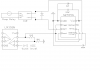
Use 4000 series logic chips to engergize DC to AC relay as needed.
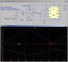
Use two differnt Op-amps with different resistors added to accomplish different gain on the incoming 0-5VDC signal.

OP-AMP 1 will be set with gain of 12 (R3=22.0kΩ, R4=2.0kΩ)
OP-AMP 2 will be set with gain of 6 (R5=10.0kΩ, R6=2.0kΩ)

Thus V1 = 6VDC at 10% (de-engergize relay)
and V2 = 6 VDC at 20% (re-energize relay)

So if I power a 4000 seires NAND gate with 12VDC, anything above 6VDC = "ON" and anything below 6VDC = "OFF".

But once the relay has bee de-engergized, I don't want it back on until after the tank has reached 20%. This means I need some kind of latching logic circuit.

I found a NAND Gate latch circuit which will do most of what I want, but doesn't allow an input state of (0,0). My quesitons are:

1. Does my circuit make sense as far as what I'm trying to do?
2. Is there an elegant way to use a NAND gate latch or something like it so as to avoid the (0,0) input problem?
3. How do I upload pics--I wasn't able to do so yet?

Thanks a lot for any help.

rsi77
 
I'm guessing that the 10% and 20% values aren't too critical? If they aren't, then I think you could set those levels simply with a Schmitt trigger gate (e.g. CD4093 or CD40106) plus a few resistors etc (I'll run a simulation to check). The gate could then drive (possibly via a buffer stage) a power FET for switching the relay or pumps.
 
Yes.

It appears that I'm trying to reinvent the wheel.

This little chip will do just what I want.

Thanks for your help.

Ron
 
Looking at it more, I'm not sure how to implement it. Perhaps I didn't read your response closely enough. The 10% and @20% have to be controlled fairly closely. Is the hystoresis on the Schmitt trigger adjustable per requirements? It seems not, but perhaps I haven't read far enough.

Can I implement this chip in such a way that I can choose my 10% and 20% at will?

Thanks,

Ron
 
Here you go....
WindowComparator.gif
Although the Schmitt threshold voltages are fixed R1 and R2 can be adjusted (they could be trimmers) to control (within reason) respectively the overall upper and lower threshold points of the circuit.
These thresholds will vary very slightly with temperature. They will also vary with supply voltage, so a regulated supply should be used.
 
Last edited:
If you want to homebrew something, here is a germ of an idea:

Start with the ubiquitous 555 timer chip. Forget that it is a timer. Think of it as a Schmitt trigger circuit that has precise trip points of 1/3 of Vcc and 2/3 of Vcc.

If pin 2 and pin 6 are tied together and it is supplied with a well-regulated 12.00V power supply, it turns on (output goes high) when the input level is below 4.00V, and it turns off (output goes high) when the input level is above 8.00V.

Pity your tank level outputs are not 4V and 8V..., but we'll get to that...
 

Attachments

  • D10a.jpg
    D10a.jpg
    156.3 KB · Views: 180
Well, if you insist on making the tank trip points 0.5V and 1.0V, then here is how...

Add an opamp which amplifies and level shifts the tank signal to match the trip points of the 555 I showed in the previous post. The Δ from 0.5V to 1.0V is 0.5V. The Δ from 4V to 8V is 4V, so the gain of the opamp must be 4/0.5 = 8. A gain of -8 will work but it will reverse the sense of the 555 output.

To get a gain of -8, R2 must be 8*R1. We also need to shift the input range so that the center of its input (0.5+1.0)/2 = 0.75V gets shifted to 6V (half way between the 555's trip points.

There is some magic offset voltage which if applied to the non-inverting input of the opamp would do that. I did some math to figure out that it had to be 1.333V. I put the formula for figuring it out into the schematic that follows.

To get the magic offset voltage of 1.333V, just put a 10K to 100K pot between Vcc (12V) and Gnd. Set the wiper to get 1.333V at the non-inverting input. It is just that easy.

The formula I derived is general enough to let you have different trip point (which changes the gain and the offset voltage).

PS: It occurs to me that the choice of 0.5 and 1.0V for the trip points was arbitrary. Can you choose resistors to make them 4V and 8V, respectively?
 

Attachments

  • D10.jpg
    D10.jpg
    253.6 KB · Views: 187
Last edited:
I'm still studying your last post, but based on the previous one, and after finding some description of how a 555 can be used as a Schmitt trigger, this 555 idea seems like a good way to go. The .5 and 1 VDC are what I will be reading at those critical tank levels from the level sensor being used. But of course I can manipulate them as necessary to suit my needs. Since my 20% and 10% tank levels are conveniently situated so that I can choose my Vcc such that it is exactly 3x of my 10% tank level voltage reading (which starts as 0.5VDC, but can become anything I wish), I can end up with the 10% level being 33% and the 20% level bein 66% of Vcc, which works out perfectly for the 555 Schmitt circuit. Additonally the 555 can deliver sufficient current at the ouput so as to diretly power my relay which will turn on and off the 120AC signal being used to control the pumps.
It seems like the perfect solution. The only thing I need to do is limit my voltage at the input so that when the tank reads > 30%, I don't damage the input (if that's possible?). If I need to I'm certain there is an easy means of of lmiting my input voltage.
BTW the same voltage I'm reading will need to be read by another PLC which is controlling the additon of liquid to the tank at he high levels. I'm assuming that using a high impedance at the input will prevent any problems "downstream" with the signal.
 
You can use a series resistor and diode to clamp the input if the input goes higher than 12V as shown:
 

Attachments

  • D10c.jpg
    D10c.jpg
    152.3 KB · Views: 172
So I built a prototype circuit on a bread board--it seems to work. Some of the values aren't exactly as predicted, but good enough for the application. It seems my Op-Amp output is limited by the supply voltage, so don't actually need the voltage limiting step.

I still need to invert the 555 output so that I have low output when I hit the low voltage threshold, and high output when I hit the high threshold. This is because the relay controlling the pumps is normally open = pumps off so that we are running in "fail-safe" mode. This seems like it should be pretty easy to do. In fact I could simply power another 555 with the output from the first one to create an inverse response. Is this reasonable?

BTW, how does one add pictures to a post--I always get an error message (bmp, png, etc.)?
 
The 555 output pin can source current about as well as it can sink it, so to invert the logic sense, connect the relay load as needed (either to Gnd or Vcc). A snubber diode across the relay coil (cathode to positive) might be a good idea, along with a bypass cap Vcc to Gnd right at pins 1 & 8. Bypass cap pin 5 to Gnd is shown on most app notes.
 
Thanks. That pretty much finishes the project. I'm going to add a couple potentiometers to adjust to uncertainty in the actual output of the level sensor vs. tank level.
Your help has made this a very easy project: first try on the bread board and it works, then to find I need only drain to the output vs. Vcc to achieve the correct polarity.
What is appropriate value for cap? The one connected to pin 5 has been recommended as .01uF--is the same good for pin 1 to pin 8?

Thanks again!

I'd like to post my circuit.
 
... then to find I need only drain to the output vs. Vcc to achieve the correct polarity.

I dont understand this.

What is appropriate value for cap? The one connected to pin 5 has been recommended as .01uF--is the same good for pin 1 to pin 8?

Put a 10uF 15V electrolytic shunted by a 0.01uF ceramic across Vcc and Gnd. 0.01uF on pin 5.

I'd like to post my circuit.

When posting, click on Go Advanced,
then Manage Attachments,
then Browse to find the graphics file on your computer,
the Upload to copy the file to electro-tech,
then Close Window to go back to the editor,
finally Submit Reply.
 
I dont understand this.

I was trying to restate (I guess incorrectly) what you had written in the prior post " so to invert the logic sense, connect the relay load as needed (either to Gnd or Vcc)".


"Put a 10uF 15V electrolytic shunted by a 0.01uF ceramic across Vcc and Gnd. 0.01uF on pin 5."

So you're adding two capacitors in parallel?. Is there a quick explanation as to the need for both caps?

Is the attached drawing correct?
 

Attachments

  • Pump Relay Cirucit.png
    Pump Relay Cirucit.png
    23 KB · Views: 181
You can eliminate the diode across the SSR's input. SSR's do not need inductive flyback protection.

Ken
 
"I would recommend that you don;t spend your time doing so. Commercial things like the IDEC smart relay would be much easier. See: https://us.idec.com/Catalog/ProductSe...ammable_Relays

You need a little investment and you could use these for other projects within the plant. A little programming and you have a standard piece of hardware that works. "


Thanks for the input. This device does look pretty handy, but from what I gathered looking at the manual, it seems it couldn't do exactly what I need without some signal conditioning at the input. That being the case it seemed almost as easy, (and definitely more fun), to make the entire circuit myself.
Ron
 
Last edited:
OK, so now I have some other question regarding how to integrate my circuit with my other electronics. As I mentioned I have a 24VDC available in the box. This 24VDC will be used to energize a number of sensors which are on other parts of the system. Here are a couple questions I have:

1. Since the current draw required for the chips and the SSR is minimal, can I assume that my circuitry won't adversely affect the readings from my other sensors which are being powered by the same supply? (SSR = Crydom D2410 (typical input current 3.4-20mA), 24VDC power supply = IDEC PS5R-SD24, rated 2.5A)

2. What is the most efficient way to step down the voltage of the 24VDC power supply, as the 555 would prefer not more than 16VDC. I was thinking a simple voltage divider, but maybe you guys know a preferred way.

Thanks,

Ron
 
The capacitors in your diagram look good.

Disc ceramics have low inductance, and do a good job of holding the Vcc to Vss voltage constant by locally supplying the current to rapidly switch the output pin of the 555 high or low. The ceramic capacitor takes care of the things that happen in ns to us.

The 10uF electrolytic stores much more charge and locally supplies current to hold the voltage constant until the upstream regulator takes over. It takes care of the things that happen in ms. Due to their construction, electrolytics are inductive, so do not work to bypass ns to us edges.

The diode on the SSR was pointed out earlier.

To get from 24V to 12V at a few tens of mA, I would use a LM7812 linear series regulator, or a TL431 shunt regulator. Even a Zener diode shunt regulator would be better than using a resistive voltage divider. Using the 555 as a Schmitt trigger with stable trip points is predicated on running it on a stable supply voltage, so you will need a regulator. Look at the recommended bypass caps to be used with the regulator(s), too.

Looks like you posted a diagram successfully.
 
Status
Not open for further replies.

Latest threads

Back
Top