Continue to Site

Welcome to our site!

Electro Tech is an online community (with over 170,000 members) who enjoy talking about and building electronic circuits, projects and gadgets. To participate you need to register. Registration is free. Click here to register now.

  • Welcome to our site! Electro Tech is an online community (with over 170,000 members) who enjoy talking about and building electronic circuits, projects and gadgets. To participate you need to register. Registration is free. Click here to register now.

How to Accurately Measure External Oscillator

Status
Not open for further replies.
Hi Nigel, Those Lowe units are prized even today. The HF-150 units on US eBay are selling for more than they were new (https://www.ebay.com/sch/i.html?_fr...RC0.A0.H0.TRS5&_nkw=lowe+hf+receiver&_sacat=0 ).

Just an update on the Banggood RTC recommended by Eric. Mine (3) arrived today. After unpacking and just plugging one in, it read 32768.001 ± 0.0005 Hz on my Racal-Dana 1992. That counter has not been calibrated in at least 10 years, so I can't say how accurate it is, but it is impressively stable right out of the box. Certainly adequate for my needs. I was also pleased with Banggood's side of the transaction. The order was processed and received in Chicago in less time than it took to get from Chicago to Cleveland.

John

Hi John,

Does the chip have a part number?

You can also heat up the chip a little and see how the frequency output behaves.
 
Mr Al can used gps disciplined standard ref oscillator if he has access to and lock the counter time base with gps .

I had an occasion to measure and adjust the Alcatel E10B electronic switch clocks to a single reference to meet data and modem service improvement.
My frequency counter was not up to mark.
then I had to seek clock from the zonal headquarters on the o f cable . sync my counter time base and then quickly use it to measure the digital switch master clocks .
All that was possible as I was working in a telecom psu

Hi,

Sounds good :)
For most of my apps i didnt want to have to receive and deal with any outside signals, except in the very distant past for an alarm clock which synced to the stable line frequency.
Dont know if the line frequency is as stable as it used to be now though, i'll have to look that up.
 
This was basically an ordinary shop on a steep hill in Matlock.

I never went to that one, and I'm not even sure where it was? - originally it was in a 'wooden hut' off Cavendish Road

The last time that I was at Lowe Electronics in the mid 1980s, he had a new place outside Matlock where you reached the shop on the upper floor by walking across a foot bridge from the carpark by the side of the road.
A curious building built on the side of a hill.

That was Bentley Bridge, it used to be a petrol station (where the car park was), it's not 'outside' Matlock, just at the outer edge of it :D

As you say, the Lowe building was reached by a footbridge, with the top floor the sales area, and the downstairs part (accessible from the rear at ground level) the service department and warehousing. There used to be a Computer Club held there (I used to attend), run by the afore mentioned John Thorpe - Lowes were the UK agents for VideoGenie (a TRS-80 clone).

There's a big secondary school behind it now, in fact my daughter went to sixth form there. The building itself is now an accounts, or something similar - Lowes was bought out by another Radio Ham company, and the original shop was closed.
 
MrAl
Chip is supposedly a DS3231 (Maxim) andboard has an AT24C32 EEPROM. If I hold the DS3231 with my thumb and index finger, I can see the frequency increase. That's a good sign and useful, 'cause it means I am still warmer than RT.

The prices for these boards are ridiculous. Cheapest on eBay whenI checked was $0.99 with free shipping! **broken link removed** By comparison, the DigiKey price for the DS3231 alone is $4,517/1000 chips.

John
 
hi John,
They are identical to the type I purchase from China.
Inbuilt IC, Temperature/RTC, they have kept very accurate timing, also they have an onboard coin cell.
E
 
Hello again,

Yes that is one of the chips i quoted previously, the DS chip.
The frequency should not change by too much when the temperature is elevated.
Yes the crystal is built in.

I bought a similar chip cost me 8 bucks back a few years ago. I got better clock timing than ever with it though.

I think you can use a digital receiver to check spectral purity of a transmitter or oscillator. If you get a strong carrier on any multiple of the base frequency you know you are transmitting more than just the carrier :)
I can pick up several frequencies just by generating a square wave less than 1MHz. I dont remember the highest i received though, but odd harmonics are abundant.
With a spectrally pure wave only the single frequency shows up.
 
ericgibbs

I agree. I left the board running for about 24 hours and the precision mentioned above stayed constant. That is, I use a 9-digit counter. All variation was in the rightmost 2 digits. Call them digits 8 and 9. When I warmed the chip with my fingers, digit 8 varied a little more than when sitting undisturbed, i.e., showed "4" instead of a "1 ", but then returned to "2" while still holding it. Of course, holding the chip like that may affect more than just the temperature. I am not complaining. Seven place and greater precision is OK with me.

The battery is an LIR2032, which is presumably rechargeable. I have read that some of these units incorporate a charger that keeps the battery up to charge while under external power. There was no mention of that in the Banggood minimalist documents. Do you know off-hand whether there is a built in charger? If not, what do you use for and at what interval do you recharge? Not surprisingly, the battery alone costs more than the whole unit.

John
 
hi John,
As you say the battery is rechargeable 3.6V L-Ion, type LIR2032
I do not have any documentation on the PCB to check for a charging circuit.
I guess the quick way would be to run the PCB for a while on its battery, check the battery voltage and then apply external power.
If a charger is present the battery voltage should be slightly higher.

Eric
 
Hi John,
I have just run that test.
Battery only 3.6V
External power connected, battery voltage rises to 3.9V dropping to 3.7V when non external, then slowly drifting back to 3.6V

I would say the PCB has an onboard charger.

Eric
 
Thanks. I was just going out the door and planned to do the same with one of my not-yet-used boards.

John
 
I would say the PCB has an onboard charger.

I suspect the term 'charger' may sound more complicated than it is, I would imagine it's nothing but a diode and a resistor to trickle charge the cell (which of course is all that's required).

I don't know what the reliability of those cells are?, but back in the days when VCR's commonly had rechargeable batteries running RTC's their life was relatively poor - and a common modification was to replace them with non-rechargeable and remove the charging resistor (this provided a longer life).

Nice test though! :D
 
Nigel,

You nailed it. Except it may be a zener (silk screen shows a "Z"). Resistor appears to be 200Ω . There are two spikes sticking out of the board. The freshly "charged" battery (since I last posted, 3.5 hours) read the same as the voltage between the spikes, 4.02V. Vcc = 4.85V. Increased Vcc to 5.2V, voltage between spikes stayed at 4.02V. Not proof, but certainly suggestive.

John
 
I've got some on ordr as well, just waiting for them to arrive from China.

I don't particularly 'need them' at the moment, but the prices are so cheap (and the delivery times so long) that it makes sense to order some 'just in case' you need them a bit later on :D
 
I paid the extra $1.70 for tracking. My total shipping time was 9 calendar days. At least 4.5 to 5 of those days were after receipt by the USPS in Chicago. In other words, I was delighted with Banggood's performance and shipping time. To me, it was well worth the extra £.

John
 
Layout is critical for reducing effects from stray coupling to near conductors and probes. If you had to add much more than the suggest NP0 cap values, it tells me your layout did not have enough coupling to a ground track around the XTAL. The CMOS Output impedance is low enough that this layout coupling to ground should not increase when a 10~30pF 10:1 10Meg probe is attached. frequency should not change at all compared to testing a counter output. ( << 0.1ppm)

I have had a lot of success with 1ppm TCXO's, 0.1 ppm OCXO's using CMOS with standard AT-cut XTALS regardless of the tolerance and stability. even 100/100 ppm types.

I have also done a lot of testing on Vectron SC cut OCXO's and used many Stratum 1,2 & 3 stable clocks in my Telecom days and before in my Doppler Design days using Navy VLF.

The Racal Dana has an SC cut OCXO, so it can't be out more than 0.001 ppm (1e-9) and is capable of 1e-11 in the short term, from my experience with SC cut XTALS ($$)

2 ppm TCXO chips are only a couple bucks these days (500pc)
1ppm a TCXO's more. 30 ppb even more.

In the 90's our team designed a TCXO using a small part of uC with tables for calibrated varicaps and microslice Xtals ( using a 10 second test) I generated the 3 rd order polynomial to compute the AT temp curve from two test points in a mini OCXO that I could switch between 40'C and 70'C with an algorithm to generate the 3rd polynomial in seconds, rather than oven sweep tests.

10 ppm watch crystals are cheap if held near optimum temp ( near 25'C)
 
Last edited:
I paid the extra $1.70 for tracking. My total shipping time was 9 calendar days. At least 4.5 to 5 of those days were after receipt by the USPS in Chicago. In other words, I was delighted with Banggood's performance and shipping time. To me, it was well worth the extra £.

I'm mean :D

I'm in no rush, as I don't actually need the parts.
 
Layout is critical for reducing effects from stray coupling to near conductors and probes. If you had to add much more than the suggest NP0 cap values, it tells me your layout did not have enough coupling to a ground track around the XTAL. The CMOS Output impedance is low enough that this layout coupling to ground should not increase when a 10~30pF 10:1 10Meg probe is attached. frequency should not change at all compared to testing a counter output. ( << 0.1ppm)

I have had a lot of success with 1ppm TCXO's, 0.1 ppm OCXO's using CMOS with standard AT-cut XTALS regardless of the tolerance and stability. even 100/100 ppm types.

I have also done a lot of testing on Vectron SC cut OCXO's and used many Stratum 1,2 & 3 stable clocks in my Telecom days and before in my Doppler Design days using Navy VLF.

The Racal Dana has an SC cut OCXO, so it can't be out more than 0.001 ppm (1e-9) and is capable of 1e-11 in the short term, from my experience with SC cut XTALS ($$)

2 ppm TCXO chips are only a couple bucks these days (500pc)
1ppm a TCXO's more. 30 ppb even more.

In the 90's our team designed a TCXO using a small part of uC with tables for calibrated varicaps and microslice Xtals ( using a 10 second test) I generated the 3 rd order polynomial to compute the AT temp curve from two test points in a mini OCXO that I could switch between 40'C and 70'C with an algorithm to generate the 3rd polynomial in seconds, rather than oven sweep tests.

10 ppm watch crystals are cheap if held near optimum temp ( near 25'C)


Hello there Tony,

I was hoping we would hear from you on this topic. I was guessing that you had some experience in this area :)

I have a couple questions.
First, have you done any long term studies on the crystal oscillators of different types?
Second, how did you fit a 3rd order polynomial with only 2 data points, or was it maybe the other way around (2nd order with 3 data points)?

Thanks :)
 
Yes
First, have you done any long term studies on the crystal oscillators of different types?
Second, how did you fit a 3rd order polynomial with only 2 data points, or was it maybe the other way around (2nd order with 3 data points)?

:)

Hi Al,

First, Yes but only briefly :)
Aging is a property of quality of materials and metallic diffusion of ions in to the crystal that can shift one way or another. It is also affected by excess heat, shock and vibration from holder movement. So the best crystals had high quality electrodes ( I forgot if they were gold plated but something that does not diffuse in to the crystal or oxidize Hence old crystal HC/U cans .were cold-welded ( Ultrasonic) an in a vacuum seal. For the last 20 years they have micro-sliced crystals in epoxy, which was notorious for being leaky to moisture and hence in the old days all plastic parts were only rated to 0'C due to pop-corn damage if any moisture go into the seal. Since moisture has a dielectric property of 60x it can add holder capacitance and lower the frequency. I don't have any vendor specific data any more, but you can always do well with some name brand crystals from Japan, like Epson.

Aging is typically 1 ppm/yr . It can slow down depending on quality of materials and process and factory source. But it never really stops as it is a slow chemical doping of crystal material from the metal holder, plus any other contaminants in contact or leaking inside.

I normally categorized all crystals with 3 numbers Tolerance/Stability/Aging per yr and temp range for stability
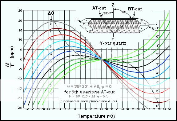
e.g. 25/25/1 -40~70'C

The polynomials I generated were manually computed with Microwave Journal's curve fitting program on DOS from digitized points all the AT temp curves which are S shaped 3rd order polynominials. Then I derived another polynomial to select which curve based on the ppm shift or slope from 40'C to 70'C because I discovered a linear relationship that could predict all the coefficients of the 3rd order polynomial for AT curves which are incremental for different crystal angle cuts in minutes ( 1/60th degree) as I recall. The crystal can micro-oven was a 2oz copper flex circuit with SMT heater resistors and SMT thermistor to sense and regulate the temperature inside a styrafoam shell. Insert XTAL, select temperature 40. wait 15 seconds. read Xtal within 0.1 ppm, switch to 70'C and repeat.. next Xtal. So they were all sorted according to angle cuts prediction by my linear PPM shift from 40~70'C then binned and paired with custom binned varistors for C1/C20V ratios so we could pair them and make a 1ppm VC-TCXO for under a dollar in parts. I don't know how others do it, but this worked.

It could also be done for other T1 to T2 temps.
7JRVslide135--ATcut.jpg


The purpose was to control the RF transceiver freq within 1ppm from -40 to +50C for ISM Band 928MHz often used by hydro companies for our unique 2 way networked automated meter reading of residential utility meters. ( MOst still walk around and use a wireless handheld unit to read the automated meter, since Spread spectrum band is too short range and noisy. Ours was networked with repeaters and tied in directly to the utility company's database, for instant meter reading or scheduled routine readings.
 
Hello Tony,

That helps explain it, thanks a lot :)
I might have to look into those crystals in more detail in the future. The ones i dealt with all had that characteristic parabolic shape. With the S curve i would think you could get at least some averaging if the temperature went up and down by roughly the same amount for roughly the same time, although i guess that's asking for a lot of luck from the environment.

When i built my first oscillator so long ago it was an RC oscillator, and i had an 8 digit frequency counter. I say many of the numbers jumping around on the display, maybe 2 steady MS digits. When i build my first crystal oscillator i then saw most of the numbers settle down to a steady value. It was interesting to see such a difference between a cheap RC oscillator and a crystal oscillator.
I also tried a voltage to frequency converter way back when, and it wasnt too bad. I think it was the 9400, which used a charge pump.
 
The AT cut crystals are used everywhere in the MHz range in both series and parallel and overtone mode.

The inverted parabola is the watch resonators 32kHz. (Usually tuning fork )

I made a FM Function Gen with a quad Op Amp with 60kHz/V and good linearity.
The cct. used a triangle gen and FET to invert polarity. It was also bipolar +/- Hz suitable for portable 3.7V pair. so 0 to 222kHz and 0 to -222kHz
using an XOR to invert the FET function.

upload_2015-9-29_16-46-8.png
 
Last edited:
Status
Not open for further replies.

Latest threads

New Articles From Microcontroller Tips

Back
Top