Continue to Site

Welcome to our site!

Electro Tech is an online community (with over 170,000 members) who enjoy talking about and building electronic circuits, projects and gadgets. To participate you need to register. Registration is free. Click here to register now.

  • Welcome to our site! Electro Tech is an online community (with over 170,000 members) who enjoy talking about and building electronic circuits, projects and gadgets. To participate you need to register. Registration is free. Click here to register now.

Junebug Prob again!

Status
Not open for further replies.

Wond3rboy

Member
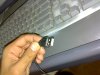
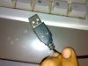
Hi sorry to pop up time and time again but i just programmed my 18F2550 with my art2003. When i plugged it in and opened mplab it said that pickit2 not found. I checked the V5v line and found that there were only 1.04v.The Chip also gets warm.I think the problem is with the USB Cable cause i couldnt find a Mount on USB male port here so i cut one from a USB extension cable.Here is how i connected it:

USB Male Port: The 3 arrow side up Left to Right.And the port is put on the top left side in my PCB(like the schematic).

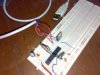
Here is how i checked the transistors:

2N3904. BC Impedance is greater then the BE Impedance.
2N3906 is opposite to the 2N2904.
2N7000 used the didoe polarity to find out the terminals.
BS250P. Used it as a switch.Found it to be working in either direction so the one in which i got more brightness of LED considered it to be Drain.

Diode:

Couldnt find a 5817 so used a 5819 instead.

Hope you guys can tell me whats the problem cause it will waste a lot of time and hardwork.Thanks.

PS: Count the money also.
 
Last edited:
It sounds like you're selfmade Junebug clone is loading your USB port.
To check communications you need only the 18F2550, crystal and it's caps, 0.47uF VUSB cap and USB connector and the caps on the power supply.
 
I can get the 18F2550,crystals and the caps.For the USB i will have to break another cable which i can do. Is there no problem in my checking of transisitor terminals?And what about the USB port wires? Are they connected correctly?
One of the power supply capacitors is .1uf(which i ahve connected non-electrolytic) and the other 100uf which is electrolytic.Are these correct values?
 
Last edited:
I just did what you said and it does not recognize the PICKit2. I will check whether the Ic is programmed and then tell you.Thanks.

Voltage is 1.75v

I've rechecked my IC, the code is present.

I connected the junebug circuit with out the IC as mentioned in your manual. I got 5.95v on U5v but the green LED did not light.

Also i did a check on the transistors and they seem to be fine(according to the terminals i listed above) but the LEDs give infinite resistance. Are they fried? And if they are then what could be causing the problem.I have checked the PCB umpteen times.The circuit is correct.The strange thing is that all 3 LED's have given way.Should i desolder them and put in new ones?
 
Last edited:
I checked the transistors again. I do have doubts about the 2N7000 pin config though but cant do any thing. If you missed it the LED's are giving infinite resistane.When i checked the 18F2550 for communication purpose it said that the computer does not recognize the USB device.Then i checked the code and it was present.After i again put it in the port. It did not do anything. No evice detected.Thanks.

PS: Sorry if i am being a headache but this is my 3 months work of begging every one to get compnents and asking how to do stuff!
 
Both the 2N7000 and BS250P can be omitted for testing. You simply jumper S&D on the BS250. Neither has anything to do with the USB part. You should have 3.3VDC across the 0.47uF cap when 5V is powering the 18F2550.

Does your programming software properly set the config bits?
 
Both the 2N7000 and BS250P can be omitted for testing. You simply jumper S&D on the BS250. Neither has anything to do with the USB part. You should have 3.3VDC across the 0.47uF cap when 5V is powering the 18F2550.

Does your programming software properly set the config bits?

The OP could perhaps reduce the C5 to 22uF.
 
Both the 2N7000 and BS250P can be omitted for testing. You simply jumper S&D on the BS250. Neither has anything to do with the USB part. You should have 3.3VDC across the 0.47uF cap when 5V is powering the 18F2550.

Does your programming software properly set the config bits?


Hi just got morning here and i did a rerun of the 18F2550 communication part and got 6.54v on the power line of the USB with out anything connected.It did not detect the PICKIT2 but on the .47 uf capacitor i got fluctuating readings of .54v,3.23v and 4.24v.I am about to tear my hair out lolz!This is really getting on my nerves! I again checked the 18F2550 program.By config bits you mean PWRTEN,WRTB,WRT0,CCP2MX,STVREN,LVP? The program is correctly written.

:confused:
Perhaps your PC or your multimeter -- one of them is faulty. please check and till then better not to plug in the PIC, as otherwise you are likely to loose it
 
Thanks for your reply Sarma.I used a 7805 for the communication part as suggested by Bill above but got nothing.It says an unkwon USB device detected.The multi meter is ok cause i checked it in another PC but got 6.8v on the USB there also.When i connected the 7805 i got a nice 4.8v.
 
Check the connection between the usb wires and the VUSB and GND pins on pic. When I see unstable reading like that (on what should be DC) I think open circuit.

If you were drawing enough current to pull the USB voltage down to less the a volt I would expect the PC to complain or shut down.

As mvs sarma said you need to check you volt meter with another.

EDIT: my bet is that you have the USB wires mixed up.
 
Last edited:
Check the connection between the usb wires and the VUSB and GND pins on pic. When I see unstable reading like that (on what should be DC) I think open circuit.

If you were drawing enough current to pull the USB voltage down to less the a volt I would expect the PC to complain or shut down.

As mvs sarma said you need to check you volt meter with another.

EDIT: my bet is that you have the USB wires mixed up.

Thats exactly what i am thinking cause i dont know how do you connect the port since i am using a cable rather than a mount on version.Thats why i asked Bill two times about my USB connections but i guess it is very hard to understand al the Left to Right stuff since one cant see it.I am uploading some pictures.This is how i have connected hte USB. The 3 arrow side up which brings the white plastic part to the bottom.The port is mounted on the top right, that way starting from the bottom(taken as ground) i go up. Is this way correct?


If i put a female port in its place and make a male male custom cross over cable will that work?Since mount on female ports are very common.
 

Attachments

  • 050220091174.jpg
    050220091174.jpg
    283.1 KB · Views: 165
  • 050220091172.jpg
    050220091172.jpg
    211.7 KB · Views: 163
Last edited:
Thanks for your reply Sarma.I used a 7805 for the communication part as suggested by Bill above but got nothing.It says an unkwon USB device detected.The multi meter is ok cause i checked it in another PC but got 6.8v on the USB there also.When i connected the 7805 i got a nice 4.8v.
7805? where?
do you mean buffered USB power supply instead of using the original power?
why not put up a little schematic of what you actually did?
 
I missed this:
If i put a female port in its place and make a male male custom cross over cable will that work?Since mount on female ports are very common.

Do not confuse USB with RS232. RS232 has a send TX and a receive RX line. USB does not work this way. The DATA+ and DATA- lines are used as a differential pair to both send and receive data.


If you make a RS232 like crossover cable you will end up with DATA+ hooked to DATA- etc. That will not work.

DATA+ need to be connected to DATA+ and DATA- to DATA-.


RS232 uses 3 wires, TX,RX and GND. To send TX and GND are used. Receive uses RX and GND.

The problem with that is that interferance can degrade the signal. To get around that USB uses a differantial signal. Instead of a GND it uses a DATA-. The DATA- signal is made negative when the DATA+ is positive. This sort of signal is much less prone to noise. That means greater speed.

Also the same differential pair is used by everyone to send and receive.
 
Last edited:
So inorder to make sure that i dont get the USB connector worng i just make a simple male male cable and connect it to the female port on the programmer?
 
Last edited:
7805? where?
do you mean buffered USB power supply instead of using the original power?
why not put up a little schematic of what you actually did?

Hi Sarma this is how i connected the 18F2550 using the communication config with the 7805.I left the DATA pins as theya re and connected the +5v to the 7805 i/p.
 

Attachments

  • 050220091175.jpg
    050220091175.jpg
    264.9 KB · Views: 168
Last edited:
3V0 i just checked my USB connections with the ones you listed. I have connected the D- and 5V lines on each others place i will correct that and have my fingers crossed. Thanks.
 
Last edited:
Status
Not open for further replies.

Latest threads

New Articles From Microcontroller Tips

Back
Top