RuairiMonahan90
New Member
Hello everyone,
This is my first post and hopefully not my last as I hope to reply and help those in need as I expand my own knowledge on circuitry (beyond that of fallout 4!). I have posted already on another website already.
I have a project which is due in a few weeks time (fast tracked course as we only received the assignment recently) and for my project I have chosen an LED roulette wheel with touch sensitive switch, which when triggered will produce the LEDs to light up one after the other until it stops on one random LED. I have researched several circuits (creating all of them on MultiSIM, which none of them worked exactly) and decided to focus on one particular circuit as I had the most success using MultiSIM (The LEDs spun once and the circuit crashed).

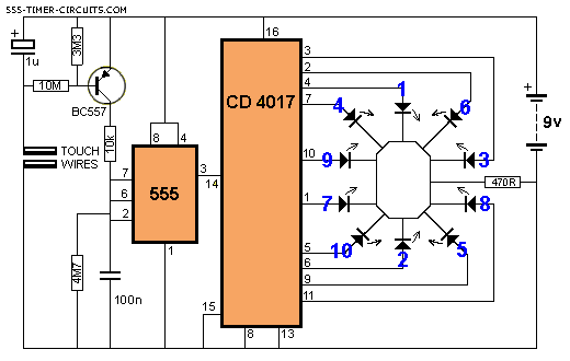
The above circuit is the one I chose. As this is a BTEC I cannot ask for help from the tutor however I am stuck in the mud right now (and usually I am quite good at building circuits both virtually and practically) as I cannot get the virtual simulation to work but more importantly I cannot get the circuit to work on a breadboard. Does anyone have any suggestions? I would really appreciate some help here and even a diagram of the breadboard just to help would be great also! Obviously I do not want someone else to do my project for me however a diagram or two would really help me as I am quickly running out of ideas and who better to ask than the experts?
This is my first post and hopefully not my last as I hope to reply and help those in need as I expand my own knowledge on circuitry (beyond that of fallout 4!). I have posted already on another website already.
I have a project which is due in a few weeks time (fast tracked course as we only received the assignment recently) and for my project I have chosen an LED roulette wheel with touch sensitive switch, which when triggered will produce the LEDs to light up one after the other until it stops on one random LED. I have researched several circuits (creating all of them on MultiSIM, which none of them worked exactly) and decided to focus on one particular circuit as I had the most success using MultiSIM (The LEDs spun once and the circuit crashed).

The above circuit is the one I chose. As this is a BTEC I cannot ask for help from the tutor however I am stuck in the mud right now (and usually I am quite good at building circuits both virtually and practically) as I cannot get the virtual simulation to work but more importantly I cannot get the circuit to work on a breadboard. Does anyone have any suggestions? I would really appreciate some help here and even a diagram of the breadboard just to help would be great also! Obviously I do not want someone else to do my project for me however a diagram or two would really help me as I am quickly running out of ideas and who better to ask than the experts?
