Continue to Site

Welcome to our site!

Electro Tech is an online community (with over 170,000 members) who enjoy talking about and building electronic circuits, projects and gadgets. To participate you need to register. Registration is free. Click here to register now.

  • Welcome to our site! Electro Tech is an online community (with over 170,000 members) who enjoy talking about and building electronic circuits, projects and gadgets. To participate you need to register. Registration is free. Click here to register now.

Uni Project Advice and Help

Nopse

New Member
I need to do the following for a project at uni:
Fixed frequency divider by 33. The counter used will have the synchronous R input. Only circuits will be used
from the HCT/HC series. The oscillator will provide two rectangular signals with frequencies of 5Hz and 435kHz respectively
and a manual clock signal.

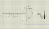
This is what I've done so far. Everything in the left side of switch 3 is mandatory. I'm new to Proteus. The simulation doesn't work, not even the first led lights up. Can someone help or give some advice please?
 

Attachments

  • Capture.PNG
    Capture.PNG
    151.9 KB · Views: 267
Can i use 7493 '4-bit binary counter' can divide by 11 with the addition of an AND gate (7408) to divide by 11 and then the block you sent me for dividing with 3?
 
And what did you do the scheme in ? What app?
ICircuit for iPad - I think it's $10. Use proteus, it's better.

Use 74161 instead of 74163 chip (I left off the HC). You'll have to change the preload value on ABCD pins to 4 instead of the current 5 value (since the 74161 resets slightly differently).
 
Can i use 7493 '4-bit binary counter' can divide by 11 with the addition of an AND gate (7408) to divide by 11 and then the block you sent me for dividing with 3?
Yes, that should work with the and gates.
 
i will count 0 - 1000001 and then reset on 1000010 but with a vary
narrow pulse, essentialy the prop delay thru the gate and the counter
rolling over from 1000001 to 1000010 to 000000.

Note 1000001 = 65

Regards, Dana.
 
I am (plesently) surprised this part is available in proteus to solve your divide by 33 problem. Let's hope the short pulse will cause a proper reset for you at the higher oscillator frequency. Yes, this part may work for you. Assuming
Per output numbering on the proteus part,
Q1 = 1
Q2 to Q5 = 0
Q6 = 1
Q7 = 0
 
What is the reason for 33 if 435k/5= 87,000d?
 
I get the impression that the clock generator designs are provided as part of the project, and the two frequencies are to prove operation of the /33 stage at both low (enough to be observable) and at a fairly high count rate??
 
What is the reason for 33 if 435k/5= 87,000d?
The 5/33 gives 6.6Hz and 9 full cycles per minute by eye. Easily counted without instrumentation. If you start from a light out until the very start of the tenth flash if connected to an LED.
 
The 5/33 gives 6.6Hz and 9 full cycles per minute by eye. Easily counted without instrumentation. If you start from a light out until the very start of the tenth flash if connected to an LED.
Clever. But I doubt that assumption were true with 1% error at best, then a 74HC' one shot could be used with a trimpot.
 
Clever. But I doubt that assumption were true with 1% error at best, then a 74HC' one shot could be used with a trimpot.
yes, that works with the 5Hz but, once the student thinks they have it nailed down, then they can connect it in the lab with a 435,000Hz signal and it must return exactly 13,181.8Hz (plus/minus) ~0.03Hz)
 
Last edited:
This might be stupid, but if you put this 7 bit counter and put Q1 to 1 of the inputs of the AND and Q6 to the other, when it hits 1000010 it should reset bcs it sends 1 logic to the reset. That should be the 33rd pulse, no? ZipZapOuch
Reading through the thread, I was hoping someone would save me the effort of posting this solution. Note that U4A can be replaced with one resistor (10K -ish) and one small signal diode such as a 1N914 or 1N4148.

ak
 
This is the sort of early experiments one tries before learning of the misteaks of asynchronous counter metastable glitches.

The divide by 33 approach given indeed works by any approach of analog AND'ing to Reset the counter long before Carry Out is reached. (Reminds me of a company in Montreal whose stock rose faster than Bitcoin invented a minutia hack for 3D finger authentication as he coined it "ANALOGIC" I was invited to RFQ quote on it, but it was not rocket science and not good authentication then the stock later tanked to $0 in 1 day.)

The pulse height of the analog Reset voltage and its PW50 or 50% peak pulse width depends on how long it takes for any gated output used to be "cleared".

This gave me the idea to make a useless fraction-N synthesizer using a capacitor on Reset as the CD4xxx gates already have high output resistance, making this a low pass filter.

The logic proposed in this question indeed counts 33 cycles by waiting the rising edge or half cycles of /2 and /64 counters of Q1 and Q6 for (2^1)/2 + (2^6)/2 binary counts to create a metastable Reset pulse = 1 + 32. Now by loading the Reset with more input capacitance, we can delay the Reset by counting more Q1 pulses until it reaches 2.5V or whatever the Reset threshold is for the IC.

Then we have a multiplier, m and a divider, n integer to create many more frequencies
f (reset) = multiplier/ divider * fclk = where the multiplier m is almost = fin/Tau for Tau = RC filter depending on the threshold tolerance for Reset.

f =m / (2^n-1) +1

Qn output labels using the binary sequence asynch. counters of the '4024'
1711639117602.png


Those who don't mind the different ways of labeling binary counter outputs won't mind the different ways of numbering compatible connector pins with multiple rows.:cool:
 
Last edited:
If the counter in the post #36 schematic is a ripple counter, there is no metastable state and no need for a R-C delay stage.

For the AND gate output to go high and reset the counter, both Q0 and Q6 mist be high. In a ripple counter there is a fixed time delay between these two outputs (the propagation delays of the intermediate counter stages), and Q0 *always* will change state before Q6. Thus, Q0 will be a 0 before Q6 becomes a 1, and that 1 will sit there without any glitches. The next clock edge will drive Q0 to a 1, have no effect on Q6, and the AND gate will drive a 1 to the Reset input.

The Q0 1 state will be very short (less than 1 us), but there is nothing in the thread so far that suggests that the Q0 output is used for anything (unless I missed something). Q6 will be a 1 for one clock cycle.

ak
 
Agree. I was responding specifically to Tony's schematic and his comment about "asynchronous counter metastable glitches." In this particular circuit, there are none. Granted that without the R-C network, the Reset pulse is very narrow. In in my experience it is reliable. This and other forums (fora?) are awash with CD4060 timer applications using this technique. Lotsa satisfied persons.

Upon reflection, it might be that this meets the technical definition of a metastable condition, since the timing is dependent on a race through a propagation delay loop.

ak
 
Last edited:
FWIW
The purpose of my cap was to stretch the Reset to enable a burst of pulses and demonstrate an analog way of making a clock multiplier with a divider aka fractional-N).
Not to mitigate a race.
Sorry for getting fancy.

The CD4024 was notorious for race glitches back in the day, with external gates to compare counts but the 74HCT4024 is improved to avoid this as it has "Balanced propagation delay and transition times"

To make the Reset on 74HCT4024 "synchronous to the negative edge clock , one must AND CLK (+) with the feedback. This will stretch the output of Reset up to 1/2 CLK cycle. There is no need to do this as the datasheet indicates a 10ns minimum Reset pulse at 4.5V @ 25'C unless the OP needs this pulse width on his divide by 33 counter. He may be interpreting the description "common reset" as "synchronous" which it is not. If it were, then the output (= reset input ) could be sampled by the CLK on one of its edges.
 
Last edited:

Latest threads

New Articles From Microcontroller Tips

Back
Top