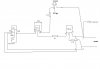
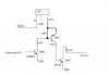
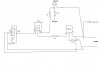
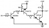
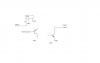
There is a small circuit schematic attached where I am using voltage regulator 7812. I input 24VDC and 12VDC comes out from OUT pin. I want to make switch off & on NPN transistor with 12VDC buy using PNP transistor before NPN. And I will use PC printer port to provide the 1 & 0 pulse of 5VDC then how I should wire the circuit I want to just get the idea. Or is there any other way to do the same?
Attachments
Last edited: