Continue to Site

Welcome to our site!

Electro Tech is an online community (with over 170,000 members) who enjoy talking about and building electronic circuits, projects and gadgets. To participate you need to register. Registration is free. Click here to register now.

  • Welcome to our site! Electro Tech is an online community (with over 170,000 members) who enjoy talking about and building electronic circuits, projects and gadgets. To participate you need to register. Registration is free. Click here to register now.

Newbie transistor question

Status
Not open for further replies.
Dan,

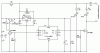
The logic will have to be reversed for my three output options..."High 4" to turn on the pulser and "Low 4" to turn it off.

Low side switching would work too.

And using the PICAXE 08M to do all the tasks...timing and pulsing...would be also possible...I think. The MARK-II ? ;) ....Just checked, and the 08M could run 3900Hz-50% duty cycle in the background with the your current timing loops.

Ken
 
Last edited:
Pommie said:
Knowing this, you could make your pic do the whole job. By switching the low side at 3kHz you will get the required output.

Mike.
I don't think so. Slopagafud said
Not switching fast at all. the Zapper is on for 10 min, off for 20, 4x. The zapper output needs to be between 5-10v @ 3khz optimal (+/- 1khz)
Looking at the picture of the Zapper, it internally generates 30kHz. Perhaps this is what he meant, instead of 3kHz. Slopagafud?
Low side switching of the Zapper directly from the PIC may not allow it to turn off completely, because of the PIC's internal diode to vcc.
 
Ron,

Think this will work for low side switching? No more 555 circuit. I needed to change the output to P2 for PWM.

Ken

Code:
Start:	'Turn on power-hold circuit

	High 1
	
OnOffOnOffOnOff: 'Operate pulser output circuit at 30KHz @ 50% Duty Cycle

	pwmout 2 , 32, 67   ‘ Pulses on P2 transistor output
  	for b1= 1 to 10
   	 wait 60   ‘ waits 60 seconds, 10 times (10 minutes)
 	  next b1
 
	pwmout 2 , 0, 0   ‘ Stop pulses on P2 transistor output
  	for b1 = 1 to 20
  	 wait 60   ‘ waits 60 seconds, 20 times (20 minutes)
  	  next b1
  
	pwmout 2 , 32, 67   ‘ Pulses on P2 transistor output
  	for b1= 1 to 10
  	 wait 60   ‘ waits 60 seconds, 10 times (10 minutes)
 	  next b1
 
	pwmout 2 , 0, 0   ‘ Stop pulses on P2 transistor output
  	for b1 = 1 to 20
   	 wait 60   ‘ waits 60 seconds, 20 times (20 minutes)
 	  next b1

	pwmout 2 , 32, 67   ‘ Pulses on P2 transistor output
	for b1= 1 to 10
	 wait 60   ‘ waits 60 seconds, 10 times (10 minutes)
	  next b1
 
	pwmout 2 , 0, 0   ‘ Stop pulses on P2 transistor output

Terminate:		'Turn of power-hold circuit

	Low 1
	Stop
 

Attachments

  • PicaxePowerSwitch9VD.gif
    PicaxePowerSwitch9VD.gif
    29.8 KB · Views: 189
Ken, I never read the other thread, and I really don't want to go back and read the whole thing. :(
Is Slopagafud trying to replace the purchased Zapper with his own design? In this thread, all I got was that he is wanting to switch the Zapper on and off with the PIC. Your new schematic looks OK, assuming that the Zapper doesn't have a transformer or some other high-voltage generating scheme. Do you know that to be the case?
 
Ron,
Slopagafud (Dan) built his own Zapper. Just a 9v 32KHz 555 astable output through a 1K resistor through a load to ground. I got in when he asked for a way to automatically run it for a series of on-off periods and shut down. I had made an auto shut off in a PICAXE circuit, so he was building on that, with someones timing loop program. I sort of messed him up when I forgot about the diodes on the PICAXE I/Os. The last circuit should eliminate the 555 portion all together.

Ken
 
The schematic I posted is scanned directly from the book "The Cure For All Diseases" by Hulda Regehr Clark Ph.D.,N.D.. She developed the device. It is the baseline ALL zappers are built from.
 
Status
Not open for further replies.

Latest threads

New Articles From Microcontroller Tips

Back
Top