tkvenki
New Member
HI everybody
i have a circuit which intends to:-(the bmp file is attached)
1) act as a inductive load to ac current(variable ac current).
2) phase shift the input current.
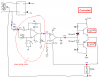
the circuit has 2 parts:-
1) Phase shifter circuit....using opamp
2)power amplifier circuit...(using TIP147 and TIP142)
I'am writing my explaination for the circuit......
1) The transformer output(the input is 230VAC) is given to a bridge which will get us +12V and -12V. This voltages help us as power supply for opamps(LM324)..and are also given to TIP147 and TIP142...this is to acheive amplification.
2) the signal comes at TP1 and that is attenuated by the 2K preset and the attenuated (it may be also left as it is) signal is given to phase shifter circuit which will result in a phase shifted signal at TP3.
3)Then the signal is somehow amplified and we get ac current at TP6.
My doubts:
1)According to my analysis the output of the darlington pair(TIP147 and TIP142) must be a square wave...But i need a sine wave for my analysis.
2)Explaination for darlington pair.
3)So i want you to tell me what will be the output at TP5??....If it is a square wave..then what i must do to get a sine wave??
4)The circuit may have some faults.....inform me if you find any of them.
Thanking you....
Venkatesh T.K
i have a circuit which intends to:-(the bmp file is attached)
1) act as a inductive load to ac current(variable ac current).
2) phase shift the input current.
the circuit has 2 parts:-
1) Phase shifter circuit....using opamp
2)power amplifier circuit...(using TIP147 and TIP142)
I'am writing my explaination for the circuit......
1) The transformer output(the input is 230VAC) is given to a bridge which will get us +12V and -12V. This voltages help us as power supply for opamps(LM324)..and are also given to TIP147 and TIP142...this is to acheive amplification.
2) the signal comes at TP1 and that is attenuated by the 2K preset and the attenuated (it may be also left as it is) signal is given to phase shifter circuit which will result in a phase shifted signal at TP3.
3)Then the signal is somehow amplified and we get ac current at TP6.
My doubts:
1)According to my analysis the output of the darlington pair(TIP147 and TIP142) must be a square wave...But i need a sine wave for my analysis.
2)Explaination for darlington pair.
3)So i want you to tell me what will be the output at TP5??....If it is a square wave..then what i must do to get a sine wave??
4)The circuit may have some faults.....inform me if you find any of them.
Thanking you....
Venkatesh T.K