Continue to Site

Welcome to our site!

Electro Tech is an online community (with over 170,000 members) who enjoy talking about and building electronic circuits, projects and gadgets. To participate you need to register. Registration is free. Click here to register now.

  • Welcome to our site! Electro Tech is an online community (with over 170,000 members) who enjoy talking about and building electronic circuits, projects and gadgets. To participate you need to register. Registration is free. Click here to register now.

grounding/earthing problem with leakage PSUs

Status
Not open for further replies.

greengold

New Member
hi all, newbie here and in electronics too.
now I want to design a circuit: MOSFET driver controlled by PWM from raspberry. MOSFET will have 220V load connected to it with about 1A current. so this is what I have:

1685736242300.png

a bit sketchy but, you'll get an idea.
first, I need to have common ground with MOSFETs source and LTV-3120 driver. otherwise it won't operate. PS2 is there only for driving it (I didn't have much luck with combination of Zenner, Caps and resistors) so there it is Whole PSU just for it. PS1 is purely for Raspberry (like) device with GPIO on it with good PWM signal and some i/o for sensors and buttons that I need.
now, both this MeanWell PSUs have 220VAC leakage to out. as per specification just with a very low current .25mA, but you can feel it, trust me. This is unacceptable. I worked around it by connecting GND1 to the Earth as you can see on the schema's top. Now this is sketchy a I know it can trip a fuste easily, but the current is small, so it runs and phase is out earthed so I can touch the pi and it's periferals.
now, I know this is all fishy, but I just don't have any idea on how to do this correctly, so I want to kindly ask you for recommendations on what should I do to minimize hazard of this circuit or straight up do it correctly? I am able to rework it still, just need some suggestions...

thank you!
 
in reality I'm using this GBP204. so far... which would be more suited?
fuse I have there, connected to mains phase but that might not be what you mean ;D

purpose in higher overview is for this 'power' circuit to drive a heatpad. that is generating a heat, sensed by temp meter hooked on RPI on which user sets desired target value and software regulates the power to get there. with PWM. so really, driving the resistive load (200W and I don't have any information on this heatpad from the reseller) with feedback loop through sensors and algo to set a duty cycle.
In the "waterbed days" of the 70's when I first got married, I had such a heater and designed a controller with a quiet relay, thermistor and Op Amp with a 12Vdc wallwort supply. It might have cycled every 15 minutes within 0.2'C . You can do the same with a Triac voltage controlled dimmer circuit. There is no need for a uC since this can be easily done with analog controls. If the thermal rate of change of 1 deg C is more than a few line cycles, ON/OFF control can work but proportional control with triac phase or PWM control of DC is easy to do and more accurate with some integration filters. But there are many sources of error so defining your expectations up front is important.

GBP204 is rated OK for 280V but may fail with lightning noise where some use CM chokes to suppress peak voltage as a filter with X & Y rated film caps to PE gnd.. Otherwise cross your fingers.

Do you care about the pad temperature or more for the target or interface temperature?
 
Last edited:
A Raspberry Pi seems massive overkill for such a simple task? You can get an off-the-shelf temperature controller module with dual display & sensing for a few pounds on ebay or amazon etc.

I've used them for similar applications, such as this DIY heating plate; I'd only just switched it on for the photo, so it's barely above ambient:

Heating_plate.jpg


If you need a custom display and controls, a small PIC or Arduino IC would do it, or Pi Pico, or an ESP32-WROOM-32 etc, if you need WiFi as well. All are a fraction the cost (and far easier to get) than the full blown raspberry pi.


Also note that most heating control applications do not need fast PWM; "burst fire" is often more suitable & you could do that with a thyristor and opto-triac for isolation, avoiding the second PSU etc. completely.


Using a zero voltage switching opto triac also vastly simplifies suppression and filtering of the controlled output; switching DC at random times in each half cycle with a FET is likely to cause RF interference, which is something you have to be very aware of in any product you are selling.
 
Please show a block diagram with all the signals/ power on each interface. I do not believe that you need all the stuff shown to do what you expect which is still not defined in point form. rjenkinsgb has shown the far better way to design this using ZCS opto Triac driver to a power Triac.
 
In the "waterbed days" of the 70's when I first got married, I had such a heater and designed a controller with a quiet relay, thermistor and Op Amp with a 12Vdc wallwort supply. It might have cycled every 15 minutes within 0.2'C .
well, more power to you :) mine is 0.2ºC in difference only when I go to target like 30ºC when room is like 20ºCish..
when I went to 45 there was a few degrees up/down difference, but in that high temps it doesn't matter much and I can still fine tune the algorithm..
Do you care about the pad temperature or more for the target or interface temperature?
temperature of the environment. as this will be enclosed in the box with some kind of shelf holding something like baking pan which will contain stuff that needs the temp. most of the time some sort of legumes (I make tempeh).
A Raspberry Pi seems massive overkill for such a simple task? You can get an off-the-shelf temperature controller module with dual display & sensing for a few pounds on ebay or amazon etc.
yeah, there were times of water beds and discmans, these are of buffering and booting ;D and even "full blown" raspberry is not of my worries. It's gonna beed to boot like for two minutes until it is operable, but idc.. in average it will run for 3days in most cases.
If you need a custom display and controls, a small PIC or Arduino IC would do it, or Pi Pico, or an ESP32-WROOM-32 etc, if you need WiFi as well. All are a fraction the cost (and far easier to get) than the full blown raspberry pi.
yes sir, I need wifi. and a controll interface on the mobile phone - an app in which you'll be able to set what kind of product are you making and fine tune the heating program. for example, when you are making a tempeh from some robust legume like chickpeas, it is a good idea to go to 42ºC every second hour for an hour and after 8hrs keep it 32ºC then ask an operator after another 8hrs if the fermentation process succesfuly started an in that cast it's gonna lower the temp to 32ºC or so, because the bacteria is generating a heat at this point as it ferments the legume.
also the there is a valid question of where to put the sensor b/c if you decide to grow mushrooms, i'll need some sterile containment and you want to place another temp sond into it, seal it and preferably don't bother it for a month or so. and yes, there will be an optional camera module to be able to take peaks in this lenghty processes.
there are simpler solutions, but trust me, if you don't know the process well enough they'll get you nowhere. you're just gonna waste sources. nobody uses them anyway. those who know what they do will do anyway, others will mostly fail. they all wait until it boots happily :))

switching DC at random times in each half cycle with a FET is likely to cause RF interference, which is something you have to be very aware of in any product you are selling.
there seems to be and interesting point however, can't tell exactly. is it about PWM freq or how often I plan to change duty cycle?
 
Please show a block diagram with all the signals/ power on each interface. I do not believe that you need all the stuff shown to do what you expect which is still not defined in point form. rjenkinsgb has shown the far better way to design this using ZCS opto Triac driver to a power Triac.
well, my point was to revise the powering here, you know. didn't want to bother you with projects specifics as I see only the type of load relevant for my question.
decided to ask for this one as powering/high voltage is dangerous and needs to be done correctly and as I screwed up (as expected) first PCB design, I'll need to pay one-time costs for documentation and whatnot once again so I figured I'll ask about this to have it sorted.
there is much more in the final schema, but it's only signalling LEDs with NOT to turn them off when the thing will be running for a month b/c some people and I know them do feel any source of light to be "radiating" sort of to them and they just don't prefer to be impacted...kind of sh** ;D --strangest times we live in.
other than that there is just 2x temp sensor interface, display connections and 3 buttons
 
give the slow thermal time constant, you can use hysteresis feedback with a short RC time lag that limits max frequency and use ON/OFF control that raises frequency towards target temp. and adjusts duty cycle for heat loss and target. But why bother with the AC bridge, make use of the DC you have. If I misunderstand the purpose, make a block diagram and draw a timing diagram.
 
yes sir, I need wifi. and a controll interface on the mobile phone - an app in which you'll be able to set what kind of product are you making and fine tune the heating program.

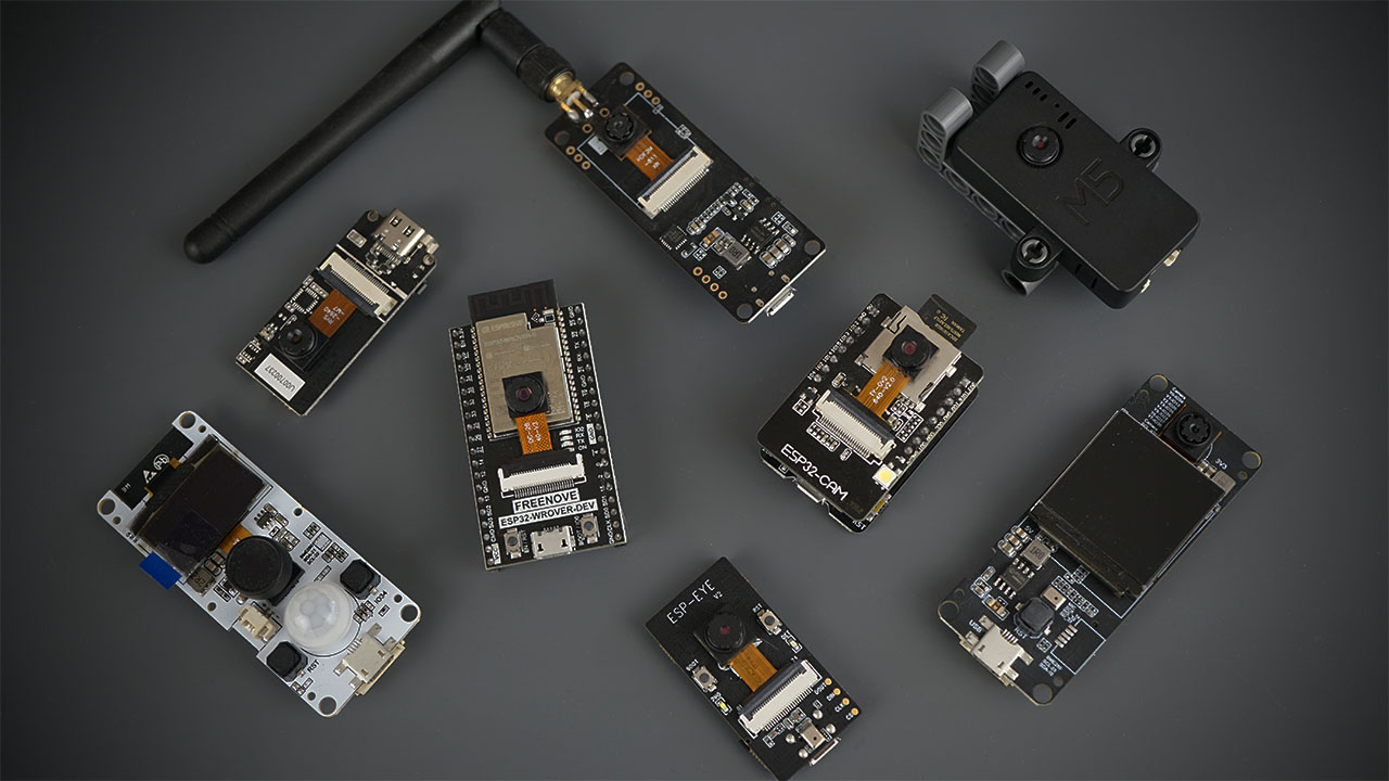
Sounds like an ESP32-CAM module would be ideal. Wifi, Bluetooth, Camera and I/O with a fast ARM CPU.
From $10, depending on the exact version.

there seems to be and interesting point however, can't tell exactly. is it about PWM freq or how often I plan to change duty cycle?

It's using PWM with a cycle time equivalent to a good few AC mains cycles - eg. 2Hz or 5Hz, with a zero-voltage switching control (which is built in some opto-triacs) so power is on or off for "bursts" of AC half cycles and never switched while voltage is present.

The control circuit is simpler and it produces little to no interference, unlike switching a load under power.

Example zero-crossing opto triac:

See page 6 of the data for the full power control circuit (Figure 9):
 
give the slow thermal time constant, you can use hysteresis feedback with a short RC time lag that limits max frequency and use ON/OFF control that raises frequency towards target temp. and adjusts duty cycle for heat loss and target. But why bother with the AC bridge, make use of the DC you have. If I misunderstand the purpose, make a block diagram and draw a timing diagram.
unfort. I don't understand you doing my best and really don't know what blocks and timing diagram you want to see.
all that is to it you basically have on the schema. more to say about it is just mC is deciding on PWM to open MOSFET as needed. that's it.
maybe i'm just doing things my way
 
If you wish to learn this language of analog , specifications , block diagrams, then we can understand what you are trying to do.

e.g. https://techweb.rohm.com/product/power-ic/dcdc/dcdc-application/10174/

https://pages.rohm.com/Tech_download17_En.html
 
Last edited:
If you wish to learn this language of analog , specifications , block diagrams, then we can understand what you are trying to do.

e.g. https://techweb.rohm.com/product/power-ic/dcdc/dcdc-application/10174/

https://pages.rohm.com/Tech_download17_En.html
like, you want to see PS sequence specification?
linear regulator..seems pretty handy, but I don't really know where this should lead me ;D look, I am here to solve this grounding/earth for two power supplies that i'm using which are comming as built package. I have the answer that it's ok just to connect the one I will use to power the mC to the earth and that it is for me.
I need to move on to other topics, but thank y'all for all the inputs.
Your suggested design is not logical to the simple task of a thermistat.
Your questions are focused on a bad design with more problems not worth fixing.

It is better to "reset" or rip up and try again with communicating the simple task of a thermistat and start by defining the interfaces for control, power and sensing.

Is this hard for you to appreciate why you are not getting what you expect?

But if all you want to know is that your DC gnds =0 V must be common, OK

AC Gnd is useful for shielding but not necessary, nor used in all household thermistats. But your approach has detailed connections but void of specs and a logical functional description.

Never connect Neutral to DC gnd.
 
Last edited:
I would have thought that there are quite a lot of circuits where DC ground is connected to neutral. However, any circuit connected to neutral (or, of course, live) must be considered potentially live and must therefore have the correct isolation to prevent electric shock.

Many transformerless supplies have a DC ground referenced to neutral.
 
Your suggested design is not logical to the simple task of a thermistat.
Your questions are focused on a bad design with more problems not worth fixing.

It is better to "reset" or rip up and try again with communicating the simple task of a thermistat and start by defining the interfaces for control, power and sensing.
look, you're free to go and create your own device. when it's better than mine than market will work for you in positive way.
no need to stand on the back foots and yell here, I have communicated my objectives here more than is need for random electronics forum with a thread named like this one is. I don't think you should be examining my overal objectives and a breakfast just as per rules. if you are just curious, you got what you wanted; i was not joking and I'm like half way through all of it. nor you are a board member of a company to discuss implementations and objectives.

good day to you
 
he's certainly green, but lacking wisdom to accept advice. its ok to learn the hard way if you want that.
 
Is this a U.S. problem? I've never experienced this in UK or Australia.

Mike.
Neutral is earth grounded at the source DT tap and sometimes at local premises, but at a circuit level Neutral suffers the same loss as line and thus shorting it on a small circuit board risks high shunt currents and makes the bridge DC ground up to 10% in theory of the line voltage for the "0Vdc" It also is common to line transients to lightning with CM coupling. So using 0Vdc from Neutral has risks.
1686014460044.png
 
Status
Not open for further replies.

New Articles From Microcontroller Tips

Back
Top