Continue to Site

Welcome to our site!

Electro Tech is an online community (with over 170,000 members) who enjoy talking about and building electronic circuits, projects and gadgets. To participate you need to register. Registration is free. Click here to register now.

  • Welcome to our site! Electro Tech is an online community (with over 170,000 members) who enjoy talking about and building electronic circuits, projects and gadgets. To participate you need to register. Registration is free. Click here to register now.

Hardware ESC 8xSERVO CONTROL on PIC (Oshonsoft BASIC)

Status
Not open for further replies.
I can't see how it's messed up. My code is outputting a pulse of 1 to 2 mS every 2.5mS to give a total time of 20mS. The servoTemp=0; is required to output the gap between pulses.
Ahhh... OK, I get the concept now, though I do not understand the reasoning for doing it that way?

Actual RC gear traditionally used literal shift register decode, with newer stuff doing it in software.
The servo pulses follow each other directly as a "1" is shifted through the SR by timed pulses received from the TX. The frame gap resets a timer and sets the SR input high until another pulse is received.

I've used my version numerous times with both standard and ultra high precision robotics servos with no jitter problems at all, as long as power and grounds are good & well decoupled. It could be very simply modified for a fixed overall frame duration if required.

If there are problems with jitter from the Oshonsoft version software, it may be that the BASIC runtime is using & blocking interrupts, possibly a timer for it's internal functions?

This is info from a current model 2.4GHz digital system - no difference in timing from my 1970s analog gear:
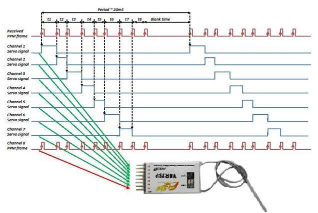
21662-1.jpg
 
Hi C,
Just looked at the conversion in post #208 and it looks pretty good and I think it should work with two changes.
1. make FRAME 20000L,
2. Move CCP1IF as indicated above by R.

I've changed both and this is the result,
Code:
'Include OSHONSOFT Basic Library
#include <xc.bas>
#include "config.bas"
#define _XTAL_FREQ 32000000
#define NUM_SERVOS 8
#define FRAME 20000L    'how long each frame is

Dim servoPos(NUM_SERVOS) As Word
Dim servoCount As Byte
Dim servoTemp As Byte

'Main Program
Sub Main()
    OSCCON = &B01110000    '8MHz
    PLLEN = 1              'x4=32MHz
    T1CON = &B00000001     'timer 1 clocks at
    CCP1CON = &B10001010   'generate interrupt only
    CCP1IE = 1             'enable CCP1 interrupts
    For i = 0 To NUM_SERVOS - 1
        servoPos(i) = i * 1000 + 8000  '1ms(8000) to 1.875(7/8ths - 15000)ms in 1/8th mS steps
    Next
    TRISB = 0              'all output
    LATB = 0
    servoTemp = 0
    PEIE = 1
    GIE = 1
    Do
        'adjust servo positions here
    Loop
End Sub

'Interrupt Routine
Sub inter()
    PORTB = servoTemp       'output as soon as possible to minimise jitter.
    If CCP1IE And CCP1IF Then
        If servoTemp = 0 Then  'which phase of the output are we in? True=just cleared output pin and started output gap
            'outputting the gap
            CCPR1 = CCPR1 + FRAME - servoPos(servoCount)   'add gap time
            servoTemp = 1 << servoCount                    'make up what is required on port B NEXT TIME
            If servoCount = 7 Then
                servoCount = 0
            Else
                servoCount = servoCount + 1
            End If
        Else
            'outputting the pulse
            CCPR1 = CCPR1 + servoPos(servoCount)   'add on time to
            servoTemp = 0                          'next time clear port B
        End If
    End If
    CCP1IF = 0
End Sub

Does this compile and if not, what are the errors?

Mike.
Edit, Actually, CCP1IF doesn't need to be moved but as there's no other interrupts it doesn't matter. For completeness, it should be above the last End If.
Edit2, FRAME is the time for 1 pulse plus the gap after it and is 2.5mS so eight frames is 20mS.
Edit3, I assume you need to change the includes to get it to compile.
Hi M,
The program a #208, won't compile, until it has the set up as in the ones I posted in #217, look at the one with M in the tile, and I can modify it as you like.
C
 
Actual RC gear traditionally used literal shift register decode, with newer stuff doing it in software.
The servo pulses follow each other directly as a "1" is shifted through the SR by timed pulses received from the TX. The frame gap resets a timer and sets the SR input high until another pulse is received.
I know they work this way, however, the overall frame-rate is fixed by the transmitter at 20mS. Some servos will work of the pulse size but some (mainly older but I do have some) jitter if the frame-rate varies. It could be because some of my R/C gear dates back to the 70s!!!!!!

Mike.
 
Ahhh... OK, I get the concept now, though I do not understand the reasoning for doing it that way?

Actual RC gear traditionally used literal shift register decode, with newer stuff doing it in software.
The servo pulses follow each other directly as a "1" is shifted through the SR by timed pulses received from the TX. The frame gap resets a timer and sets the SR input high until another pulse is received.

I've used my version numerous times with both standard and ultra high precision robotics servos with no jitter problems at all, as long as power and grounds are good & well decoupled. It could be very simply modified for a fixed overall frame duration if required.

If there are problems with jitter from the Oshonsoft version software, it may be that the BASIC runtime is using & blocking interrupts, possibly a timer for it's internal functions?

This is info from a current model 2.4GHz digital system - no difference in timing from my 1970s analog gear:

21662-1.jpg
Hi M and R,
I can see that you're having an interesting exchange between you, but for me to test your ideas, it's best if you modify each of your programs in an effort to keep it as clean as possible.

R, I can go to your program again if M's doesn't work. Remember when yours was added to the rest of the main prgram it did jitter.
EDIT: The image of timing in #221 is how I hope this will work.
C
 
Last edited:
Hi C,
Just looked at the conversion in post #208 and it looks pretty good and I think it should work with two changes.
1. make FRAME 20000L,
2. Move CCP1IF as indicated above by R.

I've changed both and this is the result,
Code:
'Include OSHONSOFT Basic Library
#include <xc.bas>
#include "config.bas"
#define _XTAL_FREQ 32000000
#define NUM_SERVOS 8
#define FRAME 20000L    'how long each frame is

Dim servoPos(NUM_SERVOS) As Word
Dim servoCount As Byte
Dim servoTemp As Byte

'Main Program
Sub Main()
    OSCCON = &B01110000    '8MHz
    PLLEN = 1              'x4=32MHz
    T1CON = &B00000001     'timer 1 clocks at
    CCP1CON = &B10001010   'generate interrupt only
    CCP1IE = 1             'enable CCP1 interrupts
    For i = 0 To NUM_SERVOS - 1
        servoPos(i) = i * 1000 + 8000  '1ms(8000) to 1.875(7/8ths - 15000)ms in 1/8th mS steps
    Next
    TRISB = 0              'all output
    LATB = 0
    servoTemp = 0
    PEIE = 1
    GIE = 1
    Do
        'adjust servo positions here
    Loop
End Sub

'Interrupt Routine
Sub inter()
    PORTB = servoTemp       'output as soon as possible to minimise jitter.
    If CCP1IE And CCP1IF Then
        If servoTemp = 0 Then  'which phase of the output are we in? True=just cleared output pin and started output gap
            'outputting the gap
            CCPR1 = CCPR1 + FRAME - servoPos(servoCount)   'add gap time
            servoTemp = 1 << servoCount                    'make up what is required on port B NEXT TIME
            If servoCount = 7 Then
                servoCount = 0
            Else
                servoCount = servoCount + 1
            End If
        Else
            'outputting the pulse
            CCPR1 = CCPR1 + servoPos(servoCount)   'add on time to
            servoTemp = 0                          'next time clear port B
        End If
    End If
    CCP1IF = 0
End Sub

Does this compile and if not, what are the errors?

Mike.
Edit, Actually, CCP1IF doesn't need to be moved but as there's no other interrupts it doesn't matter. For completeness, it should be above the last End If.
Edit2, FRAME is the time for 1 pulse plus the gap after it and is 2.5mS so eight frames is 20mS.
Edit3, I assume you need to change the includes to get it to compile.
Hi M,
I've just compared #208 with the same program in #217 which has the settings, so does compile. I can check your suggestions, above.
EDIT: Includes don't work in OSH, so they are at the top of the program.
C.
 
Last edited:
I've modified the code in #208 to what I think will work.
FRAME was defined as a word which causes more code to be generated. I don't know how to define a constant so have just put the value in the code. see CCPR1 = CCPR1 + 20000 - servopos(servocount) 'add gap time
I'm not sure what the compiler is doing behind the scene with interrupt priority etc so this may cause some jitter.
Here it is,
Code:
'18F4431 32MHz XTL REMOTE_SLAVE M 220123 1400

#define CONFIG1L = 0x00
#define CONFIG1H = 0x06  'HS oscillator, PLL enabled (clock frequency=4 x FOSC1)
#define CONFIG2L = 0x08
#define CONFIG2H = 0x3e
#define CONFIG3L = 0x04
#define CONFIG3H = 0x80
#define CONFIG4L = 0x81
#define CONFIG4H = 0x00
#define CONFIG5L = 0x0f
#define CONFIG5H = 0xc0
#define CONFIG6L = 0x0f
#define CONFIG6H = 0xe0
#define CONFIG7L = 0x0f
#define CONFIG7H = 0x40

Define CLOCK_FREQUENCY = 32
Define SINGLE_DECIMAL_PLACES = 2
Define STRING_MAX_LENGTH = 20

TRISA = %11011000  '7=OSC, 6=OSC, 4=QEIB 3=QEIA 2=TEMP SEROUT
TRISB = %00000000
LATB = %00000000
TRISC = %01000100  '6=1-slave4431_cs, 2=MOSI
TRISD = %00000000  '6=led, 7=led, 5=synch
TRISE = %00000000


ANSEL0 = 1  '[7:0]1 = Analog input: 1 = Analog input (Used later): REGISTER 21.6
ANSEL1.ANS8 = 0  '[0]Analog Input Function Select bit: 0 = Digital I/O

Disable Low
Disable High

Dim i As Byte
Dim servopos(8) As Word 
Dim servocount As Byte
Dim num_servos As Byte
Dim servotemp As Byte
num_servos = 8

T1CON=1
CCP1CON = %00001010  '7=Unimplemented on this PIC 3-0=1001 = Compare mode; initialize CCPx pin high; on compare match, force CCPx pin low (CCPxIF bit is set)
OSCCON = 0b01110000  '8MHz

RCON.IPEN = 1  '[7]1 = Enable priority levels on interrupts
PIE1.CCP1IE = 1  '[2]CCP1 Interrupt Enable bit  1 = Enables the CCP1 interrupt
IPR1.CCP1IP = 1  '[0]1 = High priority

INTCON.PEIE = 1  '[6]PEIE/GIEL: Peripheral Interrupt Enable bit: When IPEN = 1: 1 = Enables all low-priority peripheral interrupts
INTCON.GIE = 1  '[7]GIE/GIEH: Global Interrupt Enable bit: When IPEN = 1:1 = Enables all low-priority peripheral interrupts

Enable High  'This is set for SERVOS
Enable Low  'This is set for GPS later


Main_loop:
    For i = 0 To num_servos - 1
      servoPos(i)=i*1000+8000   '1ms(8000) to 1.875(7/8ths - 15000)ms in 1/8th mS steps
    Next i  'adjust servo positions here
    Do
        'adjust servo positions here
    Loop

Goto Main_loop
End                                              

'M CODE

On High Interrupt
Save System

PORTB = servotemp  'Output as soon as possible to minimise jitter.
If PIE1.CCP1IE And PIR1.CCP1IF Then
    If servotemp = 0 Then  'Which phase of the output are we in? True=just cleared output pin and started output gap
        'Outputting the gap
        CCPR1 = CCPR1 + 20000 - servopos(servocount) 'add gap time
        servotemp = 1 << servocount  'Make up what is required on port B NEXT TIME
        If servocount = 7 Then
            servocount = 0
        Else
            servocount = servocount + 1
        Endif
    Else
        'Outputting the pulse
        CCPR1 = CCPR1 + servopos(servocount)  'Add pulse time
        servotemp = 0  'Next time clear port B
    Endif
    PIR1.CCP1IF = 0
Endif

Resume

The PLL doesn't get turned on to run it at 32MHz so that needs adding.
I removed some repeated stuff so could have removed something thats needed.

Mike.
Edit, I see num_servos=8 which I assume is a constant. So, FRAME=20000 should also work, I think.
 
C can you confirm that doing CCPR1 = 0x55AA writes 0x55 to CCPR1H and 0xaa CCPR1L?

Mike.
Edit, can Ian Rogers or ericgibbs confirm this?
Hi M,
I tried to write to CCPR1 but I wasn't able to, I even tried CCPR1H but also failed, I'll have to read up about it.
My eyes are getting crossed, so it's off to bed.
G'night
C
 
Running my C code in the MPLABX simulator and using the stopwatch gives these times,
Code:
Target halted. Stopwatch cycle count = 8001 (1.000125 ms)
Target halted. Stopwatch cycle count = 8000 (1 ms)
Target halted. Stopwatch cycle count = 8999 (1.124875 ms)
Target halted. Stopwatch cycle count = 7001 (875.125 µs)
Target halted. Stopwatch cycle count = 9999 (1.249875 ms)
Target halted. Stopwatch cycle count = 6000 (750 µs)
Target halted. Stopwatch cycle count = 11001 (1.375125 ms)
Target halted. Stopwatch cycle count = 4999 (624.875 µs)
This is with a breakpoint on PORTB=servoTemp;

As you can see the times are accurate to 1 clock cycle (125uS).
This is due to the interrupt latency variation when executing a two cycle instruction.
This can only be corrected using PPS or many different CCP modules - is this a possibility?
Note, they are alternatively pulse then gap which, when paired add up to 2.5mS.

Mike.
Edit, how many servos do you actually need?
 
Last edited:
If the software approach always results in jitter, the simple fix is to add an external shift register IC, eg. a 74HC164, to feed the servos.

Connect the clock pin of that to the PIC CCP output pin, & use a normal output for the SR data in.
As the timing is then purely from the CCP hardware, minor software delays affecting the interrupt processing speed have zero effect.
 
Connect the clock pin of that to the PIC CCP output pin, & use a normal output for the SR data in.
As the timing is then purely from the CCP hardware, minor software delays affecting the interrupt processing speed have zero effect.
That would work very well and I like that approach.
However, as alluded to in the first post, the chip he's using has 8 PWM modules and he needs to control 4 servos.
PWM0 to 3 come out on RB0 to RB3 so seem ideal for jitter free control.
The thing that bothers me is, reading the manual Oshonsoft seems to take over ALL the hardware and you're supposed to use it's routines to do stuff like servos etc. so I wonder if writing direct to the hardware is even possible.

If I was doing this in C I'd start with a 1mS interrupt and every 20mS fire of all four PWM modules to generate the pulses but not even sure if a 1mS interrupt is possible.

Mike.
 
C,

What is the other pic doing? Because, if this can be done using ISR and hardware then it'll use less than 1% of the processing power and be doing nothing else.

Mike.
 
Hi M and R,
The 18F4431 is used because it has a QEI module.

I'm pretty sure that the 18F4431 doesn't have PPS.

I think I'm correct that this approach doesn't use PWMs, and as the 4431 only has 4x PWMs, this was ruled out.

Should we finalise M's approach to see if it jitters first, as I think we are close?

I think 8xSERVOS would be ok, as the extra ones could move e,g, a camera.

Adding another PIC is a possibily, but if that's the best way, then perhaps a small dedicated SERVO PIC.

The other PIC has the bigger 'brain' and is connected to 4431 via SPI, but another connecter could be added between them if necessary.
C
 
Hi M and R,
Would this work?

Switch all SERVOS on every 2000us and switch each on off as it matches it's time.
C
 

Attachments

  • SERVOS ONOFF.png
    SERVOS ONOFF.png
    11.1 KB · Views: 192
Last edited:
Sorry, missread the datasheet. I saw that it had 8 PWM modules.
pwm.png

However, these are PWM only and can't do the compare required for servo control.
The chip has only two CCP modules so can only control 2 servos.
It might be best to use R's idea of an external shift register (a 4017 would work well).

Mike.
 
You could do that but the accuracy would be way off. Only way to get total accuracy is using hardware. A shift register maybe the only way. What is the quadrature encoder connected to?

Mike.
 
You could do that but the accuracy would be way off. Only way to get total accuracy is using hardware. A shift register maybe the only way. What is the quadrature encoder connected to?

Mike.
Hi M,
Ok, accepted!

I looked at the suggested shift register, and note that it maybe a to high voltage, this PCB is mostly 3.3v.
If this is the best way then i'll look for lower voltage types.

The QEI is conetected to an incremental encoder (360°) for aiming. There is also a GPS which has an INTERRUPT too.
C.
 
Is the incremental encoder human driven? I assume that the GPS interrupt is a USART interrupt?

Mike.
Edit, are you able to switch chips?
 
Status
Not open for further replies.

New Articles From Microcontroller Tips

Back
Top