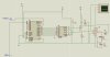
i have build this ciruit and i have distortion with negative
http://www.techlib.com/electronics/audioamps.html#LM386
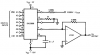
this lm324 conect to dac and the output from dac is 0.1 mv so it is too small
http://www.techlib.com/electronics/audioamps.html#LM386
this lm324 conect to dac and the output from dac is 0.1 mv so it is too small