Continue to Site

Welcome to our site!

Electro Tech is an online community (with over 170,000 members) who enjoy talking about and building electronic circuits, projects and gadgets. To participate you need to register. Registration is free. Click here to register now.

  • Welcome to our site! Electro Tech is an online community (with over 170,000 members) who enjoy talking about and building electronic circuits, projects and gadgets. To participate you need to register. Registration is free. Click here to register now.

Voltage Regulator for a Small Motorbike, 6V AC Current

Status
Not open for further replies.
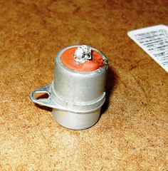
Yes, it's the original condenser. Not sure if it's the problem in points deteriation, but at 50 yrs old it may be time for a replacement. The wires from the loom were soldered onto the top, in the old fashioned way. The condenser is marked CEV 7365, which appears to be a common one for scooter and small bikes.
Not knowing the electrical values, I might as well look for one that fits the points plate. Turns out that automotive condensers are not in that style, but there are some for lawn mowers and outboard marine engines that appear close (Lawnboy, Techumseh, Sno-Jet/Yamaha, and Evinrude).

I'll hit the local shops tomorrow and see if I can find a close replacement, at least in size and mounting.

15353694970_fb51438846_m.jpg
 
The trimpot should replace R4?
I'd suggest a 1k trimpot temporarily in place of R3. Leave R4 as is.
Alex uses external heat sinks - which could work for a test, but I don't like that construction for the final version.
Agreed, not ideal. But I think a plain un-finned box may not offer enough cooling surface unless the box is large. We've been working on the assumption that the power that needs to be dissipated is 15W, whereas bulbs constantly blowing suggests perhaps 20W at least (albeit intermittent) should be the figure. Finned enclosures do exist, but are expensive, and a quick google didn't come up with any of a suitable size.
see if I can find a close replacement, at least in size and mounting.
There's a good chance the capacitance and voltage rating would be ok if the size matches.

Regarding magneto simulation, the model I've used is rather crude, with guestimated parameters. It would be nice to know the typical resistance and inductance of the magneto coil that powers the brake light, but despite a wide search of the net I've not been able to find figures for those. Any ideas?
 
Last edited:
Kiss, that's a good link on moped wire diagrams. I note that some models had a switch, so if the brake light burnt out it could be taken off the ignition circuit and the engine would still run (KTM/Foxi). Others, like the Batavus had separate coils for the head, brake, and tail lights! The last paragraph gives some explanations, saying that the brake was added-on just for the US market. That may have some truth, but I like the answer you guys gave; that it reduces the part count and it's cheaper to make two "medium" coils and fit it on that small assembly.

Sadly, the wire diagram for my bike isn't on that page, because it's considered a motorcycle.

Alec, thanks for that spec on the trimpot. I've never seen specs for the magneto coil. Is there a way for me to measure it on my bike, to improve the simulation?
 
Useful links, KISS. Good find. With info from there re magnet pole distribution and points open time I've improved the magneto modelling in the sim, but we're still short of all the facts.
Is there a way for me to measure it on my bike, to improve the simulation?
An Ohmmeter would hopefully tell us the mag's coil resistance (but not all meters measure very low resistance accurately, or at all). Inductance measurement would be trickier.
Here are some plots of simulated power dissipation in the brake-light bulb and the regulator when braking from speed at various revs (but because of model limitations don't take them too seriously). For the situation of a blown brake bulb, although some current flows through the reg it is doubtful if there would be enough spark voltage below ~3000 rpm to keep the engine running.
 

Attachments

  • Power(bulb ok, no reg).pdf
    7.2 KB · Views: 434
  • Power(bulb blown).pdf
    5.8 KB · Views: 356
  • Power(bulb ok, with reg).pdf
    9.9 KB · Views: 453
the OP said:
Alec, thanks for that spec on the trimpot. I've never seen specs for the magneto coil. Is there a way for me to measure it on my bike, to improve the simulation?

The OP has a short attention span, probably like we all do. There is too much stuff here.
https://www.banggood.com/DIY-Meter-...ntent=vera&emst=2NKh40Be80_237878_1013964_129
(almost free), or a cheap LCR meter, I brought up earlier. There is a recent discussion on ETO. For <$15.00 USD you can't not have one in your junk box. It;s a Chinese clone. Design data is available on the web and it can be improved. Nigel on ETO has one.

See: https://www.electro-tech-online.com/threads/nice-little-component-tester-kit.141912/

I updated the link. It was wrong.

With a circuit based to the LT3092 and a DVM, we could measure low resistance. https://www.google.com/url?sa=t&rct=j&q=&esrc=s&source=web&cd=1&cad=rja&uact=8&ved=0CCAQFjAA&url=https://www.linear.com/product/LT3092&ei=qak-VLjSBtHksATrmoGwCQ&usg=AFQjCNFJ7mg1SlKE9r1oeqRSGZe_gNxYpQ&sig2=lyK0PPwlgA8b7GkDCiqpSQ&bvm=bv.77412846,d.cWc

e.g. set for 50 mA and a small battery. You measure the current through the device and the voltage across the device. The banggood device claims 0.5 ohms minimum.

I measured the Cap with a portable Agilent/Keysight meter which supports multiple frequencies and is about $500 USD. alec used my data from a pump that was mailed to me for an aquarium pump controller. That thread went for more than a year. PS: I heard from Joe. No water in the tank yet. ()b is doing good things. No time for ETO.

alec: Mouser and National Instrument just introduced Multisimblue. See under reviews.

alect_t said:
For the situation of a blown brake bulb, although some current flows through the reg it is doubtful if there would be enough spark voltage below ~3000 rpm to keep the engine running.

While it could be true, apparently the only way to keep bulbs from blowing is to regulate or increase the power of the magneto. The OEM regulators that were developed shunt excess to the frame. i.e.shunt regulators.

The points pitting in 4 hours seems like a capacitor problem. Regulation could prolong bulb life, but won't keep the bike running unless alec can come up with some more magic. e.g. Hall effect current sensors in series with the bulb and in series with the regulator to somehow switch in a fixed resistor or FET. Brainstorming!

EDIT: Updated component tester link - wrong one. The one in question is a kit. So, the earlier link is wrong.
 
Last edited:
Regulation could prolong bulb life, but won't keep the bike running unless alec can come up with some more magic. e.g. Hall effect current sensors in series with the bulb and in series with the regulator to somehow switch in a fixed resistor or FET. Brainstorming!
I had been thinking idly along those lines. Detecting an open-circuit bulb then slapping a short across it is what we want, but then there is no longer an open circuit so the shorting gubbins will open again, leading to oscillation. Perhaps that's the answer; a sort of intermittent grounding of the coil. Life would be simpler if the system were DC :). I feel another sim coming on ;).
 
I'll measure the coil resistance tonight, after work. Hopefully that will give a better simulation.
Right now I'm out trying to get a new condenser.
Note, the points weren't pitted, but merely spotted. However I wasn't happy with even mere spots, after only hours of running time.
 
@sign: You measureing the resistance will be impossible. You'll get probably 0.5 to 1 ohm guessing and that will be mostly lead resistance of your DVM. If you get 10 ohms, that could be useful.
 
alec
Consider two bidirectional current sensors: Outer and bulb ( I will consider one direction). The 1 and 0 is current flow threshold detection.

Outer Inner
0...........0.........do Nothing - proper operation @ no braking
0...........1.........invalid state
1...........0.........burned out bulb
1...........1.........Proper operation

So, an "Off the wall thought": Detect the 1 0 condition and set a magnetic latching relay and switch in a load and generate some sort of warning.
You reset upon replacing the brake light. Darn: This is sounding like a micro controller. :eek:
 
@sign: You measureing the resistance will be impossible. You'll get probably 0.5 to 1 ohm guessing and that will be mostly lead resistance of your DVM. If you get 10 ohms, that could be useful.

Magneto - You are right, the error is swallowing my readings. For the coils I'm getting o.4 ohms on ignition coil, and 0.4-0.5 on the lighting coil. But that can't be 100% right, because I can tell the lighting coil has much thicker wire with fewer turns.

Points - In retrospect the spotting on the point is probably traces of corrosion, and not engine related. I cleaned and filed the points about 6-8 months ago when I went through the ignition system. It's likely that any metal, sitting for that time with no protective oil, will get the beginnings of corrosion. Rust never sleeps.
So it probably has nothing to do w the condenser/brake light, but I'm ordering a new condenser anyway by mail. The local stores all looked at me like I was asking for vacuum tubes (except for one old-timer, bless him).

Friday I'll get the components for Alec's regulator from You-do-it Electronics in Needham, MA. They're a great store, have nearly everything, and it's so much better to buy stuff in person rather than through the mail. https://www.youdoitelectronics.com/
 
Darn, for some reason I though you were in Europe. I'm on the east coast too. Although Sears should have given that away. That's why locale helps somewhat - you can taylor parts for the region. For the US, www.digikey.com, www.mouser.com and www.newark.com are the MAJOR suppliers. There is also Allied Electronics which now has an industrial twist. Jameco gets a mention and so does Ramsey Electronics (but not for parts).
 
I've used all those suppliers, but nothing beats the local guy. I'll keep you posted.

And yea, I'll have to mail order the condenser. When asking for that I got a lot of "what century do you think this is?"
 
Well, it's better then when I named my state, I got "What state is that in"? This was back in the 1980's when talking to a vendor for work.
 
For the coils I'm getting o.4 ohms on ignition coil, and 0.4-0.5 on the lighting coil. But that can't be 100% right, because I can tell the lighting coil has much thicker wire with fewer turns.
Don't worry, it's still a useful guide. If I use 0.1 or 0.5 in the sim there's only a ~1% change in the results. Except at very low rpm the resistance is outweighed by the coil's reactance (due to inductance). The inductance, and how many open-circuit volts the coil produces at any given rpm, can only be estimated without proper test gear.

KISS, a main problem with current-sensing, Hall devices, relays, micros etc is going to be the lack of volts at low revs. Ideally the blown-bulb shunt would be able to operate even at kick-start revs. Personally I'd probably settle for simply adding a manual switch to by-pass a blown bulb as a get-you-home measure.

Sign216, if it were me doing this I'd retain the old condenser as a future spare. I'd try digging out its innards and using the shell as a housing for a standard 0.3uF (or whatever) capacitor.
Simulation shows that the capacitor value shouldn't be critical. The higher the capacitance value the lower the resonant frequency of the LC circuit oscillations when the points open, the lower the HT voltage at the plug, but also lower voltage at the points and hence less arcing damage/erosion of the points.
 
I had no problem getting the condenser online. Apparently it's still a standard in the moped market.

Rather than adding a switch to take out the brakelight-ignition ground, I'll just won't use the rear brake. The circuit should be fixed soon. The front brake is the main brake anyway.

Although, I did a modification months ago that I thought would get around this. I added a resistor connecting the brake light to the ground, so that if the brake light burnt out the ignition circuit would still have an alternate path. Apparently it's not working, or I didn't wire it correctly.
 
What size resistor?

I know the power limitatations. but as always that response is mostly unworkable as is. Hey, there is always the other lighting winding, right?

So off the wall again, run a micro off lighting. The alegro hall sensors (pololu) are isolated, so you just need control.

Maybe a blown bulb detector, no regulator and switch in a resistor or load and aa buzzer?

So you see how unworkable solutions could manifest into a working one?

The brake light is a warning to others. The "hidden swich" seems the simplest and essential solution.

The rest we do for fun.
 
Status
Not open for further replies.

Latest threads

New Articles From Microcontroller Tips

Back
Top